Graphene oxide particles and method of making and using them

a graphene oxide and particle technology, applied in the field of graphene oxide particle production, can solve the problems of woefully inefficient and ineffective systems in their performance and economic aspects, battery life is very limited, and most batteries (even rechargeable ones) tend to lose their ability to hold electrical charges, etc., to achieve high purity, improve performance, and improve efficiency

Active Publication Date: 2019-05-16
KING ABDULLAH UNIV OF SCI & TECH
View PDF0 Cites 3 Cited by
  • Summary
  • Abstract
  • Description
  • Claims
  • Application Information

AI Technical Summary

Benefits of technology

[0028]The present invention is an improved method of production of graphenic materials used to store energy and the energy storage systems using such produced graphenic materials. The methods of production in the present invention have demonstrated surprising efficiencies and effectiveness in resolving long-standing problems associated with large-scale production of commercially viable, adequately sized, and uniformly configured graphene, graphene oxide, and graphenic materials used in supercapacitor applications. The graphene oxide produced by the methods described herein exhibit improved performance relative to previously known carbon-based supercapacitor materials, including being highly effective at producing sheets of graphenic material of minimum required sizes, with significantly high levels of purity and reduced levels of negative reactants, all produced in more efficient, less time consuming and more economically feasible methods than are known to exist before this invention.

Problems solved by technology

Electrical energy storage systems using electrochemical capacitors and batteries have been used in the past, but such systems have been woefully inefficient and ineffective in their performance and economic aspects.
Batteries have a very limited life-span with most batteries functioning until the battery components or chemicals have been depleted of their available electrons, which usually necessitates discarding the battery.
While some batteries can be re-charged, most batteries (even rechargeable ones) tend to lose their ability to hold an electrical charge over time, which necessitates the replacement of the depleted battery.
With the advent of miniaturized electronic devices, chemical energy storage systems have not kept pace with the need for smaller, faster, and longer lasting electrical energy storage systems that provide faster, higher capacity portable energy for miniaturized electronic devices.
While reduced graphene oxide (rGO) has a graphene-like structure, chemical reduction processes cannot result in complete restoration of the sp2 surface structure because substantial defects, such as holes or gaps, in the graphene lattice are still generated and present after the chemical restoration process.
These lattice defects have a significant impact on the mechanical and electrical properties of graphene oxide (GO) and reduced graphene oxide (rGO).
A long-felt and unresolved problem with the use of graphene, graphene oxide (GO) and reduced graphene oxide (rGO) as a component in electronic equipment is that only a small quantity of graphene can be synthesized from graphite from existing processes, such as mechanical exfoliation or chemical vapor deposition (CVD).
Commercially viable methods of large scale production of graphene, graphene oxide (GO) and reduced graphene oxide (rGO) are not achievable with known systems and methods.
The large-scaled synthesis of graphene or graphenic material having the desired properties has proven to be a difficult problem to solve, and many skilled experts in the field have failed to find a proper solution to this problem.
The lack of a process and system capable of such large scale synthesis of graphene and graphenic material is a long felt need in the state of the technology, which is entirely unresolved at the present time.
Many failed attempts have been made to solve the large-scale synthesis of graphene and graphenic materials through the use of mechanical exfoliation or chemical vapor deposition (CVD) methods and systems.
These attempts to use mechanical exfoliation or chemical vapor deposition (CVD) methods and systems have not satisfactorily resolved the need for commercially-viable large scale synthesis of graphenic materials.
Although the mechanical exfoliation methods can produce high quality single layer graphene, it is not commercially viable due to the high production costs involved.
Graphene produced by mechanical exfoliation has a high degree of purity, but it is time-consuming and can be difficult to produce sheets that are large enough for many applications, which (combined with other difficulties) have been largely insurmountable problems encountered when attempts have been made to scale up mechanical exfoliation processes into a large-scale production method or system.
Until the advent of the present invention, the large-scaled synthesis of a consistent graphene or graphenic material having the desired properties has proved to be a difficult task that is a long felt need in the state of the technology, and the prior art mechanical exfoliation processing techniques have failed to achieve large-scale synthesis of a uniform graphene or graphenic material by resolving the significant production problems associated with this technique.
The CVD method is relatively effective at producing sheets of the required size, but the graphene produced by this method carries a significantly high level of impurities (mainly from the catalyst used in the process).
Such CVD processes have proven to be time-consuming and largely economically infeasible (expensive), which have been significant unresolved problems in the past when attempts are made to scale up CVD processes into a large-scale production method or system.
These prior art chemical exfoliation techniques have failed to achieve large-scale synthesis of a uniform graphene or graphenic material by resolving the significant production problems associated with this technique.
As such, these prior art chemical exfoliation methods and systems have not resolved the need for commercially-viable large scale synthesis of graphenic materials.
Graphene and graphene oxide (GO) produced by these chemical exfoliation techniques has a high degree of impurities and produces problematic by-products.
These prior art techniques are also time-consuming and have proven difficult to produce large-scale sheets of graphene or graphenic material that are sufficiently-sized for many applications.
These unresolved problems continue to exist when attempts are made to scale up these chemical exfoliation processes into a large-scale production method or system.
The large-scaled synthesis of a consistent graphene or graphenic material having the desired properties has proven to be a difficult task that is a long felt need in the state of the technology, and the prior art chemical exfoliation processing techniques have failed to achieve large-scale synthesis of a uniform graphene or graphenic material by resolving the significant production problems associated with this technique.

Method used


Image

  • Graphene oxide particles and method of making and using them
  • Graphene oxide particles and method of making and using them
  • Graphene oxide particles and method of making and using them

Examples


example 1

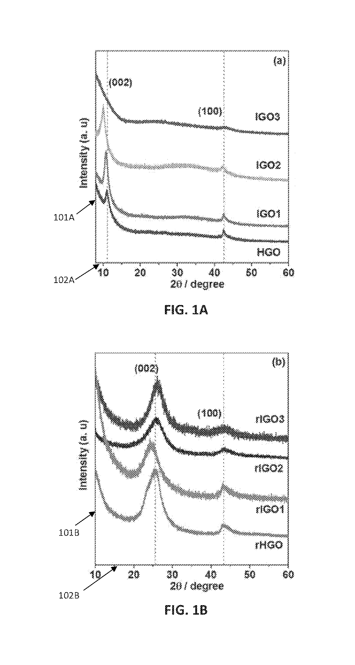
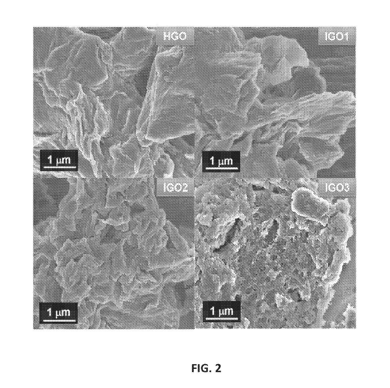
of Graphene Oxides (IGO1, IGO2, and IGO3)

[0089]Graphene oxides were produced according to the following method, which are exemplary. Times, temperatures and pHs useful for the disclosed method of graphene oxide production are not limited to the times, temperatures and pHs used in the examples herein.

[0090]Graphite powder (Sigma-Aldrich, catalog #332461) (3.0 g) was added to a mixture of 40 mL H3PO4 and 360 mL concentrated H2SO4, and the resulting suspension was stirred in an ice bath for 2 h, and then KMnO4 was added according to Table 1, below.

TABLE 1SampleGraphite (g)H3PO4 (mL)H2SO4 (mL)KMnO4 (g)IGO13.0403609.0IGO23.04036018IGO33.04036027

[0091]Each resulting mixture was stirred for 1 h in an ice bath, and then 100 mL water was added to each mixture. After stirring for 10 min, each mixture was removed from the ice bath and then heated to 90° C. in an oil bath for 60 min. After cooling to room temperature, Na2CO3 was added until the pH of the mixture reached about 7.2. An excess of ...

example 2

of a Comparative Graphene Oxide (HGO)

[0092]A comparative graphene oxide was produced according to Hummer's method. Graphite powder (Sigma-Aldrich, catalog #332461) (3.0 g) was added to a mixture of 1.5 g NaNO3 in 75 mL H2SO4, and the resulting suspension was stirred in an ice bath for 2 h, and then 9.0 g KMnO4 was added.

[0093]The resulting mixture was stirred for 1 h in an ice bath, and then 100 mL water was added. After stirring for 10 min, the mixture was removed from the ice bath and then heated to 90° C. in an oil bath for 1 h, and after cooling to room temperature, Na2CO3 was added until the pH of the solution reached about 7.2.

[0094]An excess of ethanol was added, and the solution was centrifuged at 9000 rpm. The collected solids were washed with HCl, then water, and then ethanol until the effluent reached pH of about 7, and then the solids were isolated.
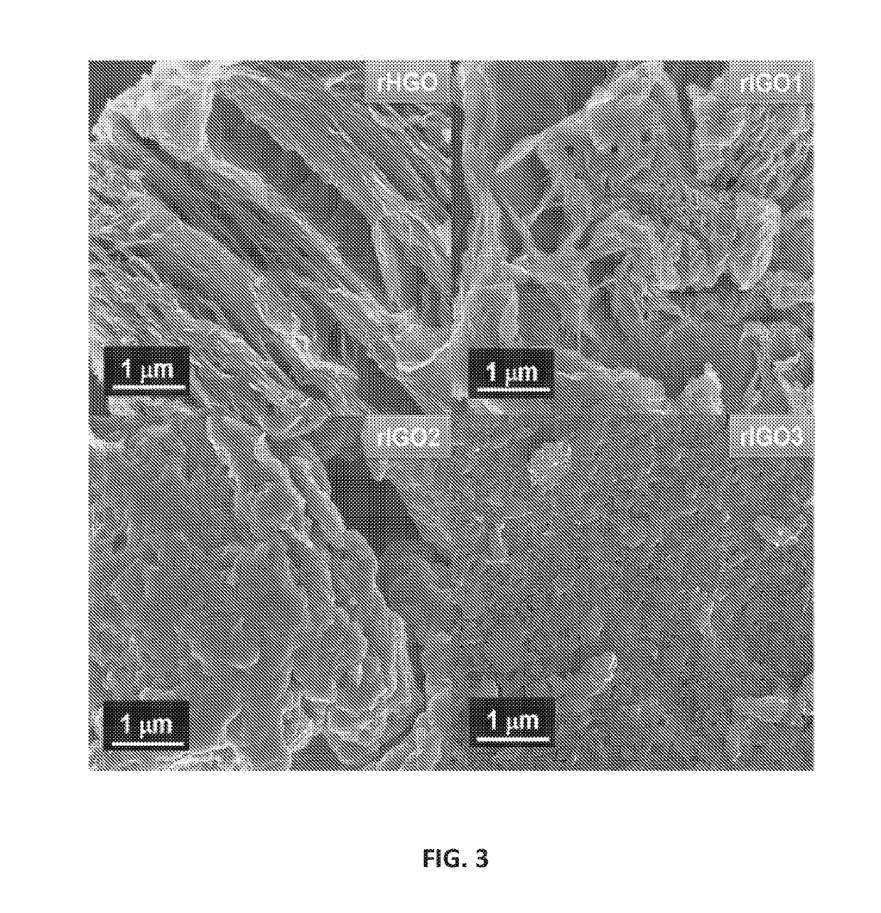
example 3

mal Reduction of Graphene Oxides

[0095]Sample of about 50 mg of each graphene oxide (IGO1, IGO2, IGO3, and HGO) were placed in 40 mL aliquots of water and the resulting suspensions were ultrasonicated for 15 min, and then subjected to 180° C. for 24 h. Solids from each sample were isolated by filtration, washed with water, and then dried at 60° C. under vacuum. The reduced forms of IGO1, IGO2, IGO3, and HGO are termed rIGO1, rIGO2, rIGO3, and rHGO, respectively.


PUM

PropertyMeasurementUnit
timeaaaaaaaaaa
temperatureaaaaaaaaaa

Abstract

The present invention is an improved method of production of graphenic materials used to store energy and the energy storage systems using such produced graphenic materials. Provided herein is a method of producing graphene oxide that includes oxidizing graphite powder in a mixture of H3PO4 and H2SO4 in the presence of KMnO4, wherein the ratio of graphite powder to KMnO4 is about 1:9 by weight and the ratio of H3PO4 to H2SO4 is about 1:9 by volume, to produce graphene oxide; dispersing the graphene oxide in water at an acidic pH (e.g., about 0) to form a solution; adjusting the solution to about a neutral pH; and isolating the graphene oxide. An energy storage device is provided herein that includes the graphene oxide made by the disclosed methods or that includes the population (plurality) of reduced graphene oxide particles having the properties disclosed herein, such as batteries and supercapacitors.

Description

RELATED APPLICATION DATA[0001]This application claims the benefit of U.S. Provisional Patent Application Ser. No. 62 / 343,527 filed May 31, 2016.TECHNICAL FIELD[0002]The present invention relates a method of production of graphenic materials used to store energy and energy storage systems using such produced graphenic materials.BACKGROUND OF THE INVENTION[0003]The background of this invention will address Electrical Energy Storage Systems, Electrochemical Capacitors and Graphene Oxide matters.[0004]Electrical Energy Storage Systems[0005]Electrical energy storage systems using electrochemical capacitors and batteries have been used in the past, but such systems have been woefully inefficient and ineffective in their performance and economic aspects. For instance, electrical energy storage systems that use batteries rely on chemical reactions between the components to produce electricity. In the chemical reaction, a battery releases electrons from certain constituent components and che...

Claims


Application Information

Patent Timeline
Patent Type & Authority Applications(United States)
IPC IPC(8): C01B32/198C01B32/23H01M4/587H01G11/36H01G11/86
CPCC01B32/198C01B32/23H01M4/587H01G11/36H01G11/86C01B2204/22C01P2002/72C01P2004/03C01P2002/88C01P2002/82C01B2204/32C01P2002/85C01P2006/40C01P2006/12C01P2004/50C01B32/192Y02E60/13Y02E60/10
Inventor RASUL, SHAHIDCOSTA, PEDRO M.F.J.ALAZMI, AMIRA
Owner KING ABDULLAH UNIV OF SCI & TECH
Why Eureka
Try Eureka