
Apparatus and method for inducing vibrations in a living body

a technology of living body and apparatus, applied in the field of medical devices, can solve the problems of reducing the effectiveness of guidewires and catheters that transmit vibrating energy to intravascular sites, reducing reducing the effectiveness of intravascularly introduced intravascular devices, etc., to achieve the effect of enhancing the ability of intravascularly introduced intrabody devices, speeding up drug delivery and/or penetration and absorption, and enhancing the action of lysing

Inactive Publication Date: 2007-11-29
INTEC RES
View PDF20 Cites 5 Cited by
  • Summary
  • Abstract
  • Description
  • Claims
  • Application Information

AI Technical Summary

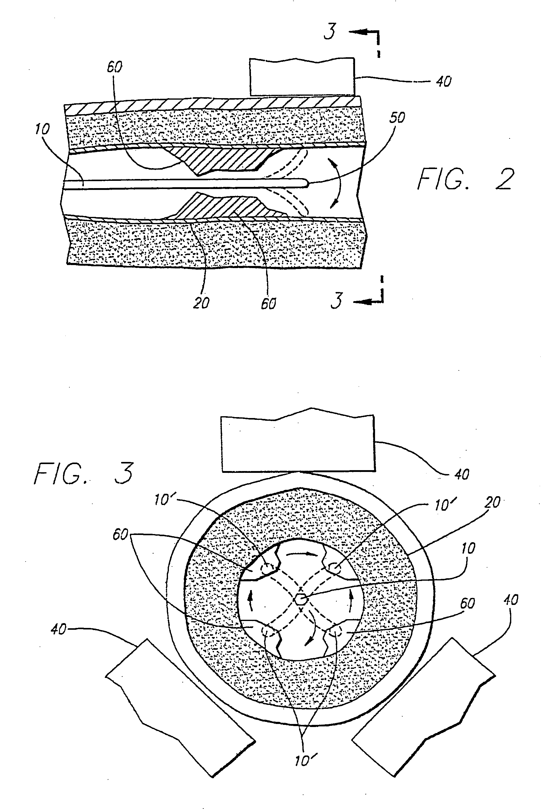
Benefits of technology

[0010] The present invention addresses the above mentioned needs by providing a method for generating vibrations within the body of a patient in a simple, economical manner with minimal risk and substantial flexibility. The method relies on equipment that is simple and economical to manufacture with a high degree of reliability. At its most basic, the method of the present invention entails the introduction of any one of a number of devices known in the art including, for example, intravascular devices such as guidewires or catheters, into a patient's body and positioning the device such that a predetermined portion of the device lies adjacent to the target site. The predetermined portion of the device incorporates a ferromagnetic or ferrimagnetic material, that is, a material that is susceptible to the attractive effects of magnetic fields. A pulsed magnetic field source, that is, a source that changes over time in magnitude and / or direction, of sufficient strength is disposed outside the patient's body in sufficient proximity to the intrabody device to induce motion in the device through the oscillating magnetic field that it emits. In this manner, a vibrating action is induced in the intrabody device of a frequency proportional to the frequency at which the magnetic source field pulsates.
[0011] By increasing or decreasing the frequency of the magnetic source field, the vibrating frequency of the intrabody device can be increased or decreased as well, and in this manner the intrabody device can be vibrated at sufficiently high frequencies to generate ultrasonic waves within the patient's body. By varying the strength of the magnetic field generated by the magnetic source, the amplitude of the mechanical vibrations generated by the intrabody device and their impact upon the surrounding tissue and other matter can be varied as well. Therefore, a physician employing the method of the present invention retains compete control over the procedure and can tailor the treatment to closely match the individual requirements of each patient.
[0012] In practice, the magnetic source is preferably an electromagnet connected to an alternating current source that causes the electromagnet to emit an oscillating magnetic field that changes polarity at a frequency matching the frequency of the alternating current source. To enhance the intrabody device's vibrating motion, a pair of such electromagnets disposed on opposite side of the patient's body and supplied by alternating current sources at out-of-phase voltages may be employed so that the electromagnets alternatingly attract the intrabody device in opposite directions. Alternatively, two or more electromagnets may be spaced around the intrabody device and each supplied with alternating current that is out of phase with the alternating current being supplied to the other electromagnets, so as to give rise to a three dimensionally oscillating magnetic field and affect the plane and direction of vibration of the magnetic material, thereby inducing three dimensional vibratory motion within the device.
[0014] An intrabody device vibrated by the method of the present invention can be introduced intravascularly and used to break up thrombi or other masses through its mechanical vibrating motion or through waves generated by the intrabody device, or to enhance the action of lysing agents and other drugs by speeding up drug delivery and / or penetration and absorption into tissue. Such a device would be helpful in breaking up clots and emboli which cause ischemic stroke, myocardial infarction, deep vein thrombosis, pulmonary emboli, and other intravascular clots. In addition, the method of the present invention can be used to enhance the ability of an intravascularly introduced intrabody device to navigate the sometimes tortuous pathways of a patient's vasculature. The method of the present invention may also be used to induce vibrations in intravascularly disposed devices other than guidewires and catheters, such as stents and other permanently deployed devices for the purpose of reducing or eliminating clots that may have formed upon the device or otherwise affecting the body's response to such implants such as reducing vasospasms.
[0015] For the purpose of breaking up a thrombus through mechanical or ultrasonic action, it may be useful to equip the alternating current source driving the electromagnetic source with the ability to constantly vary the frequency, the amplitude, or both the frequency and the amplitude of the alternating current that it supplies. In this manner, the vibrations or ultrasounds emitted by the intrabody device can continuously sweep up and down over a predetermined range of frequencies so as to repeatedly impact the thrombus at its contemporaneous resonance frequency and thus greatly speed up the process of breaking up the thrombus. Because each thrombus is a heterogeneous structure, its resonance frequency range will vary according to its age, makeup and other variables. By continuously sweeping up and down over a range of frequencies, the intrabody device will repeatedly hit upon the resonance frequency of different portions of the thrombus regardless of how often or to what degree new clots are being formed, thereby greatly enhancing the efficiency end effectiveness with which the thrombi are dissolved without the need to somehow measure or gauge the various resonance frequencies of the thrombi present at any point in time.

Problems solved by technology

Although the types of devices discussed above have met with varying degrees of success, they all suffer from some common limitations.
Erstwhile, guidewires and catheters that transmit vibrating energy from an outside source to an intravascular site quickly lose effectiveness when they are disposed along a tortuous pathway or if they are highly flexible, and most of the vibrating energy is lost in the tissue surrounding the wire.
In addition, some of the prior art reports that such guidewires have been known to break when sonic power was applied.
Devices that carry the vibration generator at their distal tip for insertion into the patient's body are necessarily limited by the physical constraints imposed by such generators, which must be relatively large to create significant power, and thus preclude any meaningful use in certain applications such as neurovascular intervention.
And although physical size is not a constraint with devices such as the Rosen pulsed energy catheter, such devices are relatively expensive, are somewhat difficult to use, and can generate significant heat with the attendant potential for tissue damage.
This catheter therefore simply utilizes magnetic coupling as parts of its transducer mechanism, and suffers from the same limitations of energy losses due to friction and heat generation in to the surrounding tissue, as well as relative bulk and difficulty of deployment within the vasculature.
In addition, this too is a relatively complex, uneconomical device.
While it appears that favorable results have been obtained with this method, it presents the potential for overheating the tissue of the patient disposed between the acoustic lens and the thrombus, as well as the tissue surrounding the thrombus.
In addition, the ultrasound generator is specified in the 10 to 50 KW range and produce as much as 100 W / cm2, which is a rather large amount of energy to apply to a living body and would seem to limit the duration of treatment for this method.

Method used


Image

  • Apparatus and method for inducing vibrations in a living body
  • Apparatus and method for inducing vibrations in a living body
  • Apparatus and method for inducing vibrations in a living body

Examples


Embodiment Construction

[0019] The present invention addresses the need for physicians and other medical personnel to be able to induce vibrations at a localized target site within a patient's body for any number of purposes, such as breaking up a thrombus or enhancing the action of medical drugs. The present invention provides a method for inducing vibrations in a manner that is simpler, safer, and more efficient and effective that previously known in the art.

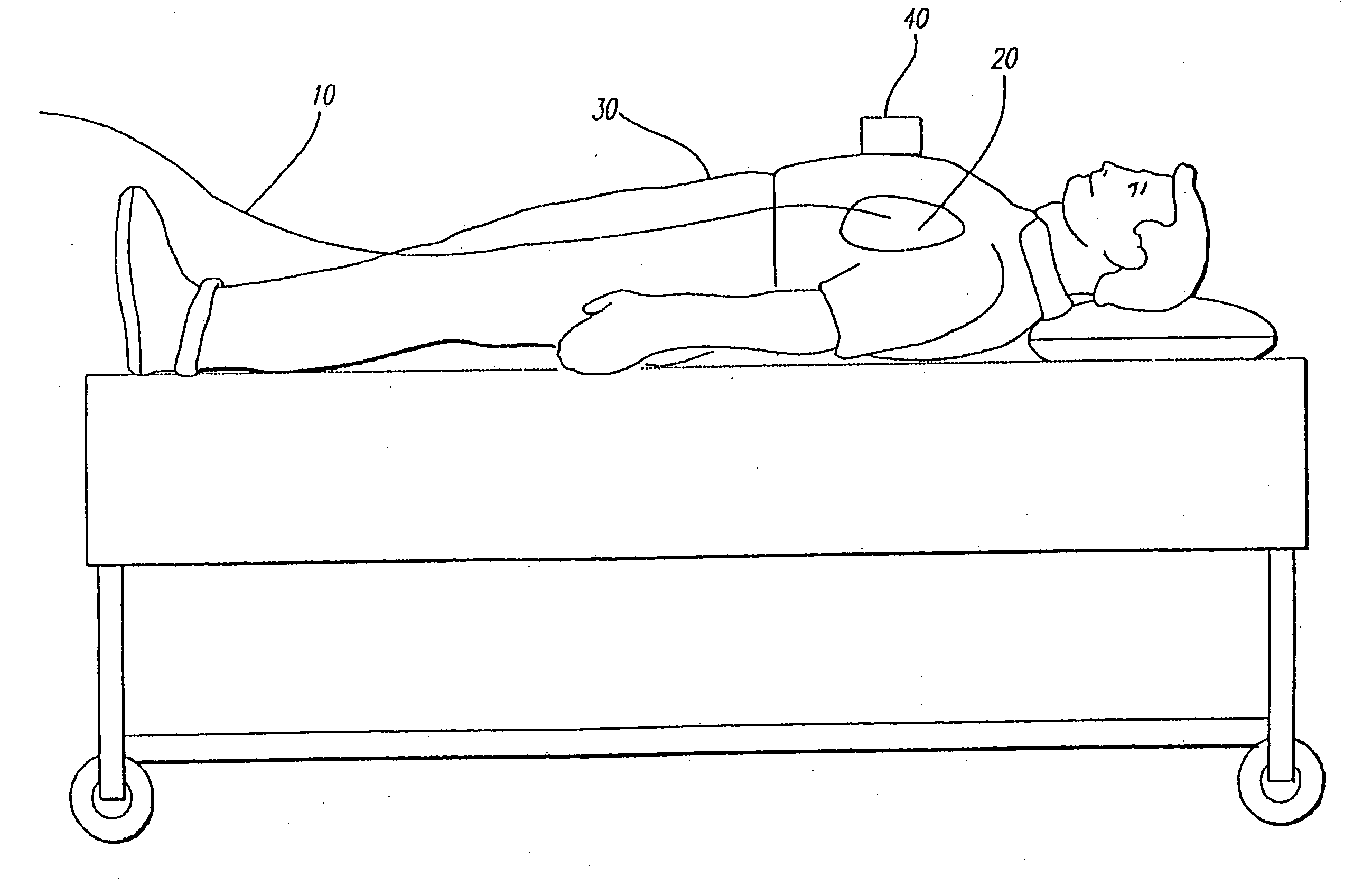
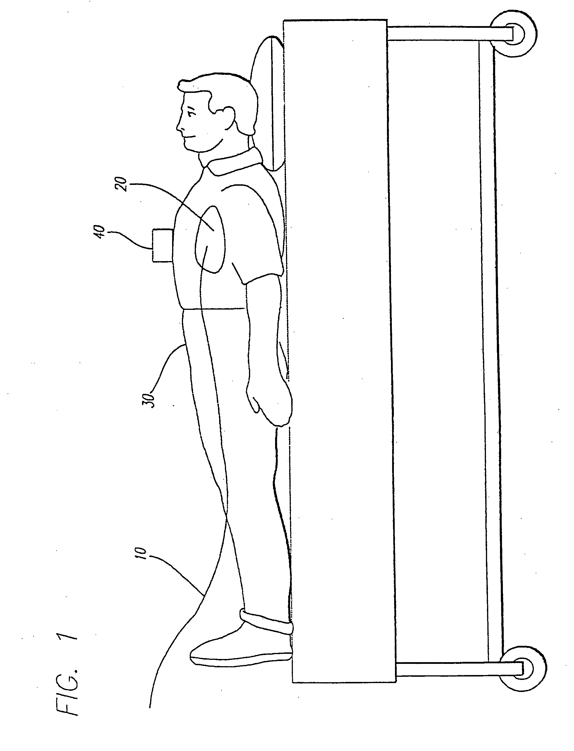
[0020] With reference to FIG. 1, the method of the present invention entails the placement of an object 10 to be vibrated in proximity to the target site 20 within the patient's body 30. The object may be an intravascular device introduced to the target site through the patient's vasculature, such as a guidewire (as shown in FIG. 1), a catheter, or a similar device. However, the method of the present invention may be employed equally efficaciously with other types of devices, including immobile devices such as stents, oils, clot traps, and filters, ...


PUM


Abstract

A medical device incorporating magnetic material is introduced into the body of a patient. A time varying magnetic field is generated externally of the patient's body and which is of sufficient strength to magnetically induce motion in the device, thereby causing the medical device to vibrate within the patient's body. The frequency and the amplitude of the magnetic field oscillations can be continuously varied to control the vibrations induced in the medical device.

Description

[0001] This application is a continuation application of U.S. patent application Ser. No. 10 / 340,438, filed Jan. 9, 2003, which is currently pending; which is a continuation of U.S. application Ser. No. 10 / 007,755, filed Oct. 25, 2001, abandoned; which is a continuation of U.S. application Ser. No. 09 / 107,879, filed Jun. 30, 1998, abandoned.BACKGROUND OF THE INVENTION [0002] The present invention relates to medical devices, and more particularly to a new method for inducing vibrations in such devices while they are disposed within a living body. [0003] Vibrating medical devices, such as intravascular devices used in intravascular intervention, have been known in the art for some time and have been employed for a variety of uses. Such uses include, for example, facilitating the advancement of a catheter or guidewire through the vasculature to a target site by reducing the vessel wall friction encountered by the device, and breaking up thrombi and other intravascularly disposed masses...

Claims


Application Information

Patent Timeline
IPC IPC(8): A61B5/05A61B17/22A61B5/00A61N2/02A61N2/10
CPCA61B17/22012A61B2017/22042A61N2/02A61N2/002A61B2019/2253A61B34/73
Inventor BROWN, PETER S.ZANELLI, CLAUDIO
Owner INTEC RES
Learn More