Cooling system with compressor bleed and ambient air for gas turbine engine

a gas turbine engine and compressor bleed technology, which is applied in the field of turbine engines, to achieve the effect of increasing the cooling effect and increasing the cooling flow to the turbine blad

Inactive Publication Date: 2017-11-21
SIEMENS ENERGY INC
View PDF17 Cites 2 Cited by
  • Summary
  • Abstract
  • Description
  • Claims
  • Application Information

AI Technical Summary

Benefits of technology

[0005]A cooling system for a turbine engine for directing cooling fluids from a compressor to a turbine blade cooling fluid supply as compressor bleed air and from an ambient air source to the turbine blade cooling fluid supply to supply cooling fluids to one or more airfoils of a rotor assembly is disclosed. The cooling system may include compressor bleed conduit extending from the compressor to the turbine blade cooling fluid supply that provides compressed air as cooling fluid to at least one turbine blade to cool the turbine blade during start up and cool down procedures. In one embodiment, such configuration may be used together with an ambient air cooling system for the turbine blade. In another embodiment, the compressor bleed conduit may include an upstream section and a downstream section whereby the upstream section exhausts compressed bleed air through an outlet into the downstream section through which ambient air passes. The outlet of the upstream section may be generally aligned with a flow of ambient air flowing in the downstream section. As such, the compressed air energizes the flow of ambient air, increasing the cooling flow reaching the turbine blade and increasing the cooling effectiveness. Such configuration may be useful during start up and cool down procedures when pumping action is less than necessary to pump ambient air.
[0012]An advantage of the cooling system is that the cooling system uses compressor bleed air during startup and shutdown procedures to help feed ambient cooling air to the turbine blade cooling fluid supply when there is not enough pumping power to draw ambient air into the ambient air supply inlet. During engine start, compressor air is often bled into the exhaust to prevent compressor stability problems. The cooling system uses a portion of that compressor bleed air which would otherwise be wasted and uses it in the ambient cooling system where there is not enough pumping power.
[0013]Another advantage of the cooling system is that the cooling system includes valves that enable the compressor bleed to be shut down once normal operation has been achieved and sufficient pumping action is occurring within the last stage of the turbine blades to draw ambient air into the ambient air supply inlet and be exhausted into the blades.

Problems solved by technology

Turbine blades, vanes and other components often contain cooling systems for prolonging the life of these items and reducing the likelihood of failure as a result of excessive temperatures.

Method used


Image

  • Cooling system with compressor bleed and ambient air for gas turbine engine
  • Cooling system with compressor bleed and ambient air for gas turbine engine
  • Cooling system with compressor bleed and ambient air for gas turbine engine

Examples


Embodiment Construction

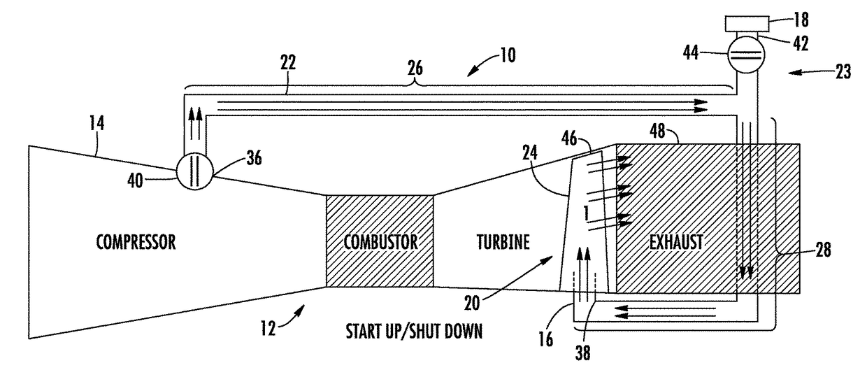
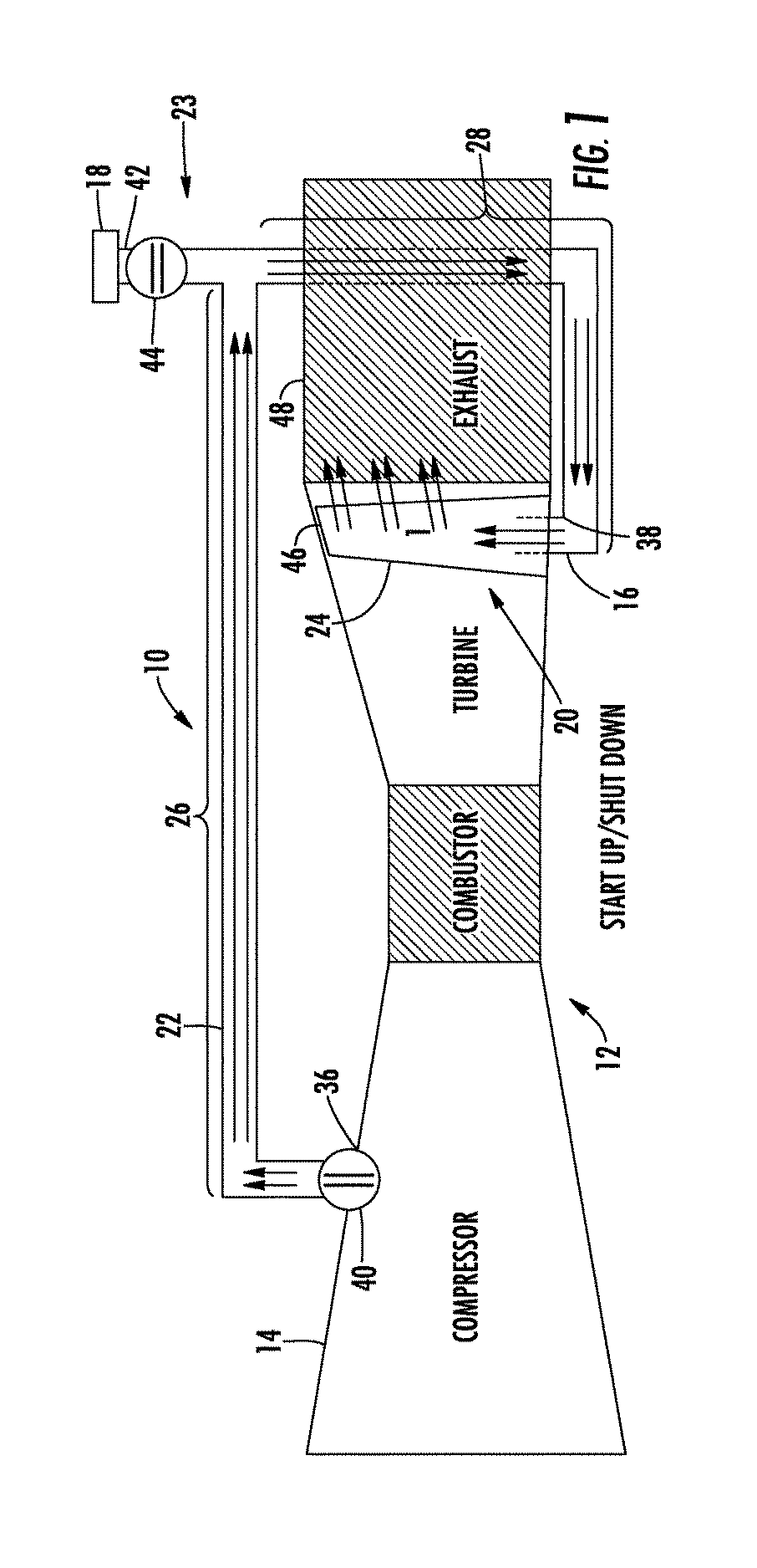
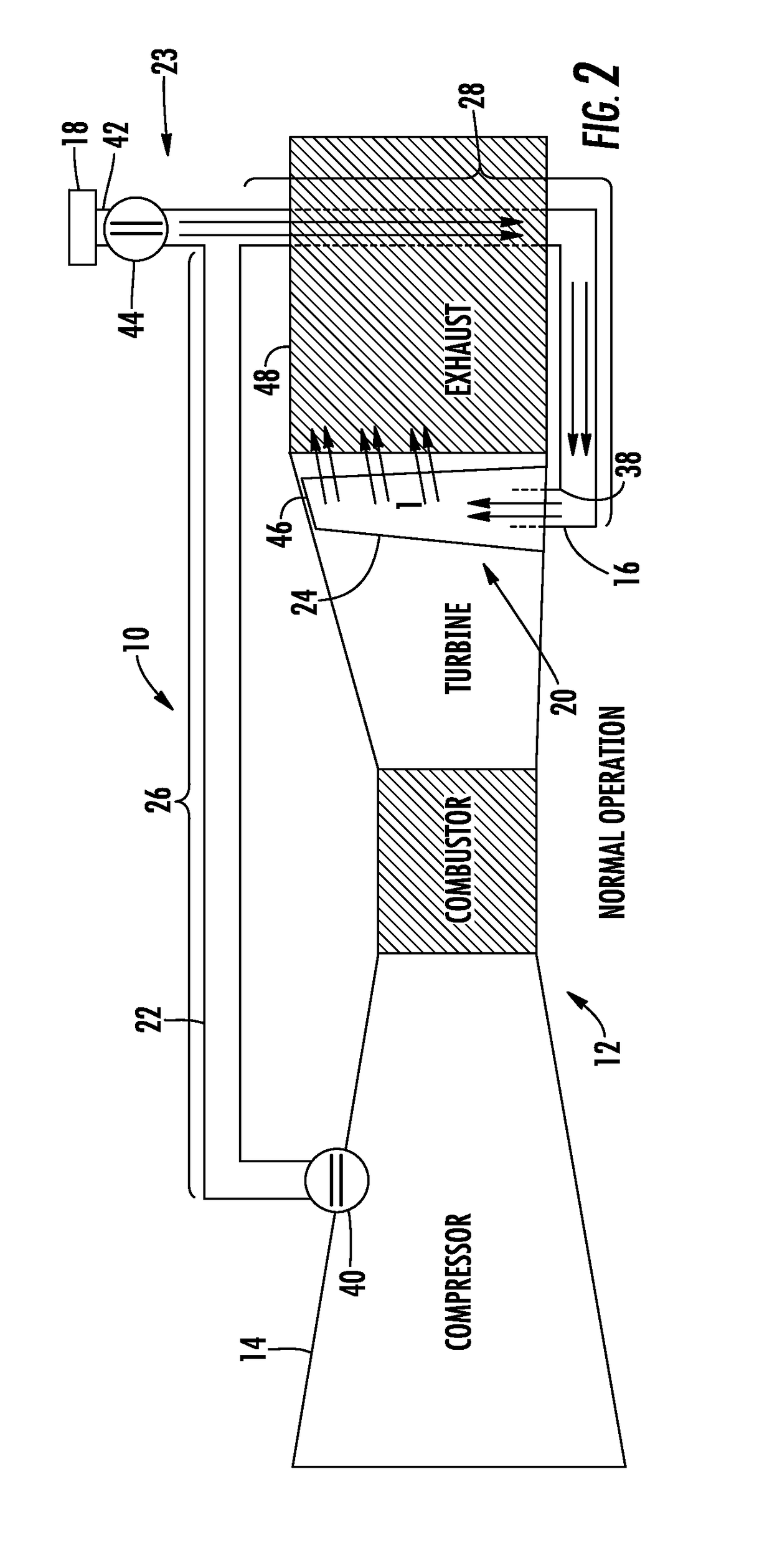
[0019]As shown in FIGS. 1-3, a cooling system 10 for a turbine engine 12 for directing cooling fluids from a compressor 14 to a turbine blade cooling fluid supply 16 and from an ambient air source 18 to the turbine blade cooling fluid supply 16 to supply cooling fluids formed from compressed air or ambient air, or both, to one or more airfoils 20 of a rotor assembly 22 is disclosed. The cooling system 10 may include compressor bleed conduit 22 extending from the compressor 14 to the turbine blade cooling fluid supply 16 that provides compressed air as cooling fluid to at least one turbine blade 24 to cool the turbine blade during start up and cool down procedures. In one embodiment, such configuration may be used together with an ambient air cooling system 23 for the turbine blade 24. In another embodiment, the compressor bleed conduit 22 may include an upstream section 26 and a downstream section 28 whereby the upstream section 26 exhausts compressed bleed air through an outlet 30 ...


PUM


Abstract

A cooling system for a turbine engine for directing cooling fluids from a compressor to a turbine blade cooling fluid supply and from an ambient air source to the turbine blade cooling fluid supply to supply cooling fluids to one or more airfoils of a rotor assembly is disclosed. The cooling system may include a compressor bleed conduit extending from a compressor to the turbine blade cooling fluid supply that provides cooling fluid to at least one turbine blade. The compressor bleed conduit may include an upstream section and a downstream section whereby the upstream section exhausts compressed bleed air through an outlet into the downstream section through which ambient air passes. The outlet of the upstream section may be generally aligned with a flow of ambient air flowing in the downstream section. As such, the compressed air increases the flow of ambient air to the turbine blade cooling fluid supply.

Description

STATEMENT REGARDING FEDERALLY SPONSORED RESEARCH OR DEVELOPMENT[0001]Development of this invention was supported in part by the United States Department of Energy, Advanced Turbine Development Program, Contract No. DE-FC26-05NT42644. Accordingly, the United States Government may have certain rights in this invention.FIELD OF THE INVENTION[0002]This invention is directed generally to turbine engines, and more particularly to cooling fluid feed systems with ambient cooling air for turbine airfoils in gas turbine engines.BACKGROUND[0003]Typically, gas turbine engines include a compressor for compressing air, a combustor for mixing the compressed air with fuel and igniting the mixture, and a turbine blade assembly for producing power. Combustors often operate at high temperatures that may exceed 2,500 degrees Fahrenheit. Typical turbine combustor configurations expose turbine blade assemblies to these high temperatures. As a result, turbine blades and turbine vanes must be made of mater...

Claims


Application Information

Patent Timeline
Patent Type & Authority Patents(United States)
IPC IPC(8): F01D25/12F02C7/12F02C6/08F02C7/18
CPCF01D25/12F02C6/08F02C7/185F02C7/12F05D2260/601F05D2220/3215
Inventor MARSH, JAN H.MARRA, JOHN J.
Owner SIEMENS ENERGY INC
Why Eureka
Try Eureka