Steel cord and conveyor belt

Active Publication Date: 2017-11-28
YOKOHAMA RUBBER CO LTD
View PDF17 Cites 3 Cited by
  • Summary
  • Abstract
  • Description
  • Claims
  • Application Information

AI Technical Summary

Benefits of technology

[0008]According to the steel cord of the present technology, with the lubricant provided between the wires that constitute the core strand, when the rubber product embedded with the steel cord is in use, the wires that constitute the core strand slide against one another very smoothly. Thus, hysteresis loss of the rubber product attributable to slip resistance between wires can be reduced. Additionally, the core strand is centrally disposed in the steel cord, and thus the lubricant adversely affecting the adhesion between the rubber o

Problems solved by technology

For example, in the case of a conveyor belt rubber product, operating with high hysteresi

Method used


Image

  • Steel cord and conveyor belt
  • Steel cord and conveyor belt
  • Steel cord and conveyor belt

Examples


examples

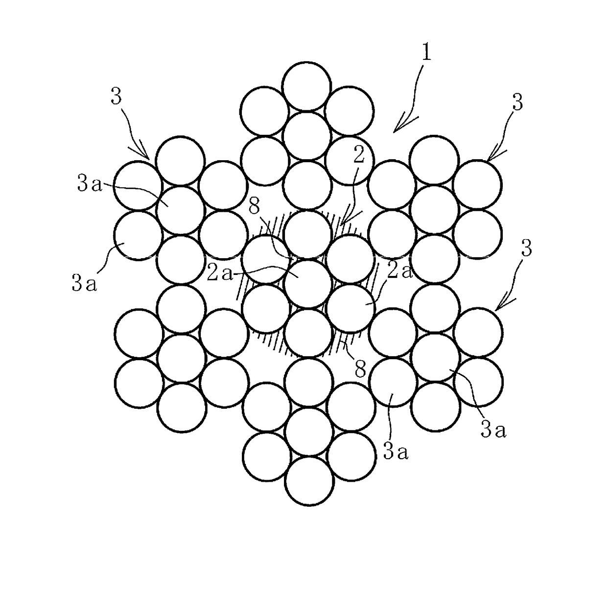
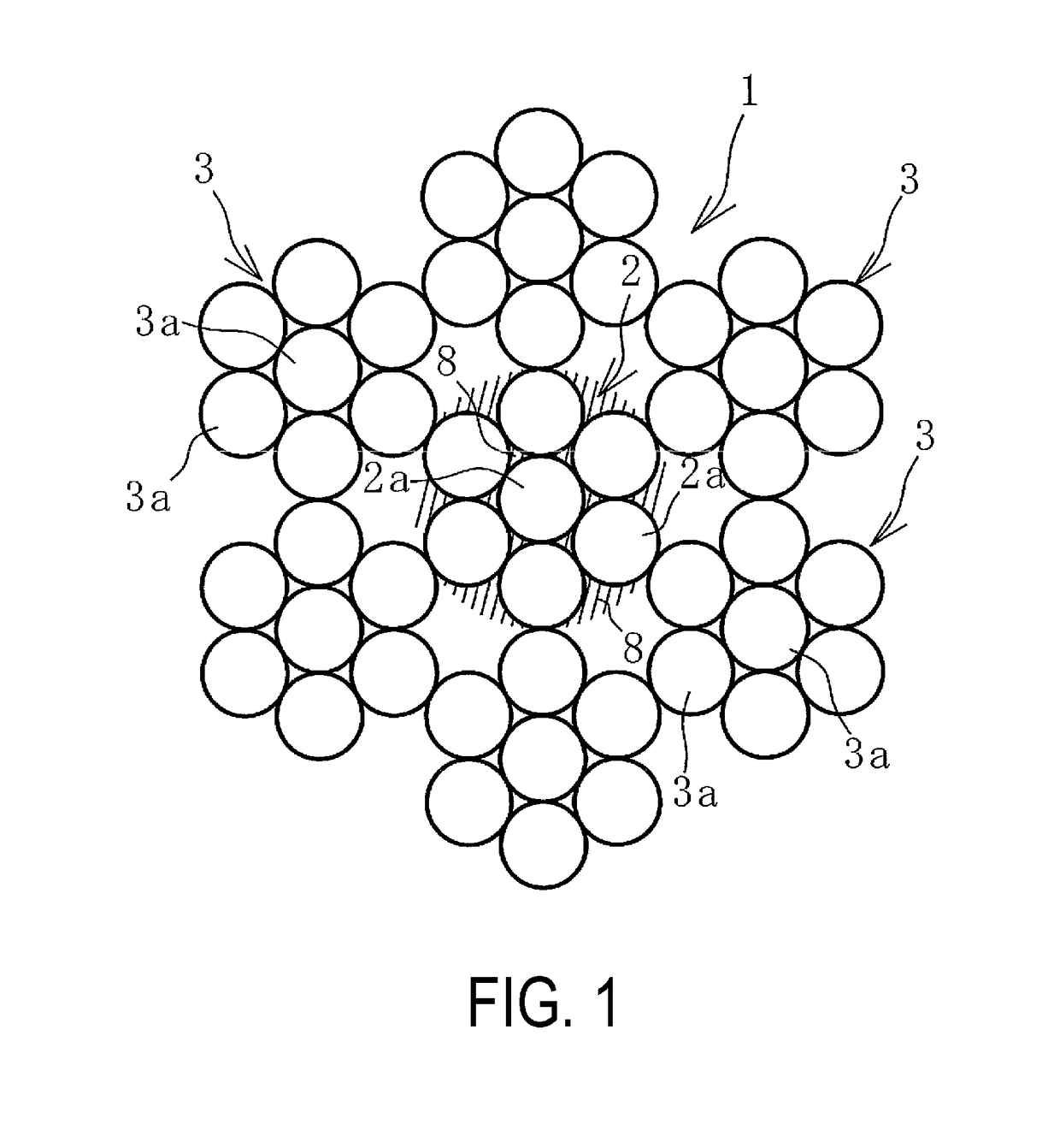
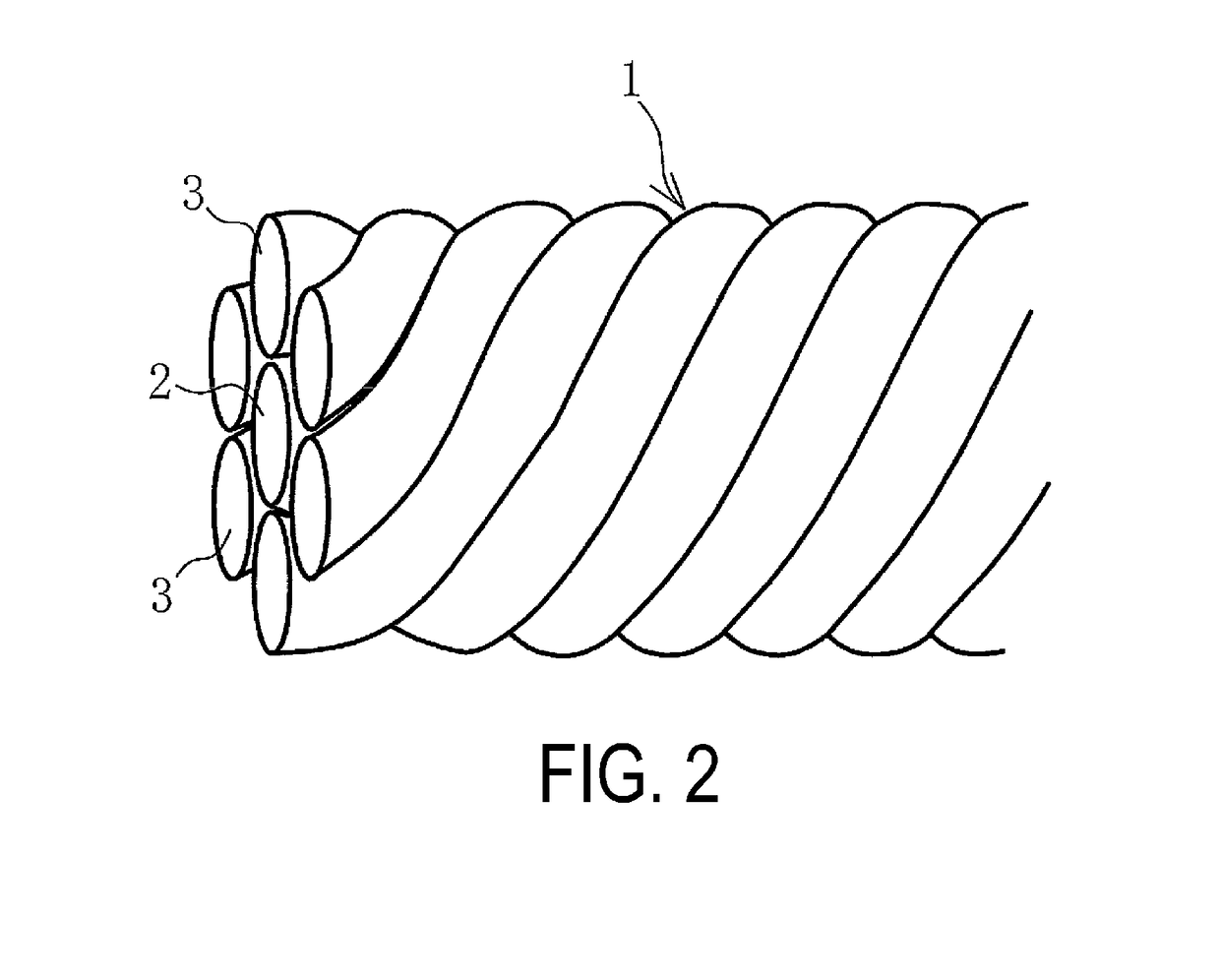
[0033]7×7 structured steel cords (4 mm cord diameter) were used to prepare samples (Cord Working Examples 1 to 3) in which three lubricants with differing kinematic viscosities were provided between the wires that constituted the core strand; and 7×7 structured steel cords (4 mm cord diameter) were used to prepare a sample (Cord Conventional Example) in which a lubricant was not provided. Each of these samples were embedded in an unvulcanized rubber, then the rubber was vulcanized. The Cord Working Examples 1 to 3 used aroma oils with differing kinematic viscosity as the provided lubricant. The kinematic viscosities of the three aroma oils were 8 mm2 / s at 40° C., 55 mm2 / s at 40° C., and 55 mm2 / s at 100° C. The amount of the lubricant provided (immersion amount) to the steel cords 1 was from 1 g / cm3 to 2 g / cm3, both inclusive. Next, a steel cord sample was taken from each of the vulcanized rubbers. Using samples of a predetermined length, a predetermined bending test was performed to...


PUM

PropertyMeasurementUnit
Temperatureaaaaaaaaaa
Fractionaaaaaaaaaa
Kinematic viscosityaaaaaaaaaa

Abstract

A rubber-reinforcing steel cord embedded in a rubber product has a stranded structure including a core strand, and a plurality of sheath strands intertwined around an outer circumferential surface of the core strand; wherein a lubricant is provided between wires that constitute the core strand.

Description

TECHNICAL FIELD[0001]The present technology relates to a steel cord embedded in a rubber product and a conveyor belt. The present technology particularly relates to a steel cord embedded in a rubber product capable of reducing hysteresis loss attributable to the steel cord when the rubber product is in use and a conveyor belt with the steel cord embedded as a core.BACKGROUND ART[0002]Steel cords constituted by steel wires intertwined together are used as reinforcing members in tires, conveyor belts, rubber hoses, and other rubber products. A steel cord is known that has a stranded structure of a plurality of sheath strands intertwined around the outer circumferential surface of a core strand (for example, see Japanese Unexamined Patent Application Publication No. 2012-036539A). To manufacture these rubber products, a reinforcing layer formed of an arranged plurality of steel cords is embedded in an unvulcanized rubber member to form a molded article. Thereafter, the molded article i...

Claims


Application Information

Patent Timeline
IPC IPC(8): B65G15/36D07B1/06D07B1/14
CPCB65G15/36D07B1/0613D07B1/144D07B2501/2076D07B2201/2058D07B2501/2046D07B1/0646D07B1/0653D07B2201/2046D07B2201/2062D07B2205/502D07B2801/24D07B1/06
Inventor HOU, GANGMIYAJIMA, ATSUSHISUEFUJI, RYOTAROSASAKUMA, HIDEHIRO
Owner YOKOHAMA RUBBER CO LTD
Why Eureka
Try Eureka