Wire electrical discharge machining device

a wire electrode and machining technology, applied in the direction of manufacturing tools, electrical-based machining electrodes, electric circuits, etc., can solve the problems of wire electrode breakage, unduly large energy, etc., and achieve the effect of reducing tension, increasing set tension, and reducing set tension

Active Publication Date: 2017-12-05
SODICK CO LTD
View PDF131 Cites 2 Cited by
  • Summary
  • Abstract
  • Description
  • Claims
  • Application Information

AI Technical Summary

Benefits of technology

[0009]In many cases, a tension on the wire electrical discharge machining has been set to a sufficiently large value in order to maintain high machining accuracy. Energy for the electrical discharge machining determines a material removal rate, that is, a machining efficiency. However, the energy for the electrical discharge machining has been suppressed in order to prevent wire breakage. The energy for the electrical discharge machining is mainly determined by the machining conditions for a current pulse, such as a current peak Ip, ON-time and OFF time. It is considered that generating a current pulse with a large peak current to a high frequency contributes to high-speed machining.
[0010]In one embodiment, the present invention is to provide a wire electrical discharge machining device which can improve a material removal rate while preventing wire breakage. In addition, the other object of the present invention is to provide a wire electrical discharge machining device which can improve a material removal rate without losing machining accuracy. In order to achieve the above-mentioned objects, a wire electrical discharge machining device of the present invention includes a tension controller for controlling a set tension of a wire electrode according to a wire breaking tension at which the wire electrode breaks.
[0012]When the set tension is less than the allowed tension, the set tension generation module can increase the set tension in such a way that the set tension does not exceed the allowed tension. The tension is increased to a degree at which the wire electrode does not break; therefore, a very straight wire electrode can be obtained.
[0013]When the set tension is greater than the allowed tension, the set tension generation module can reduce the set tension in such a way that the set tension does not go below a predetermined lower limit. The predetermined lower limit can be determined according to machining accuracy, for example. The tension is reduced to a degree at which machining accuracy is not decreased; therefore, wire breakage can be prevented without losing machining accuracy.
[0014]The tension controller can further include a wire breaking risk determination module for determining a wire breaking risk, and a margin generation module for generating a margin based on the wire breaking risk. The allowed tension calculation module calculates the allowed tension by subtracting the margin from the wire breaking tension. The wire breaking risk is determined according to a pressure of a machining fluid supplied to the machining gap (3), for example. Even if the fluid pressure decreases sharply due to a breakdown or a shape of the work, and the wire breaking risk is increased, the tension controller can decrease the wire breaking risk promptly.
[0015]The wire electrical discharge machining device of the present invention calculates the allowed tension based on the wire breaking tension at which the wire electrode breaks, and changes the set tension to the allowed tension; therefore, wire breakage can be effectively prevented. In addition, energy for electrical discharge machining is not necessary to be unduly limited from the point of view of the wire breakage; therefore, a material removal rate can be improved.

Problems solved by technology

However, an unduly large tension may cause undesirable breakage (wire breakage) of the wire electrode.
Unduly large energy for electrical discharge machining is also easy to cause wire breakage.

Method used


Image

  • Wire electrical discharge machining device
  • Wire electrical discharge machining device
  • Wire electrical discharge machining device

Examples


Embodiment Construction

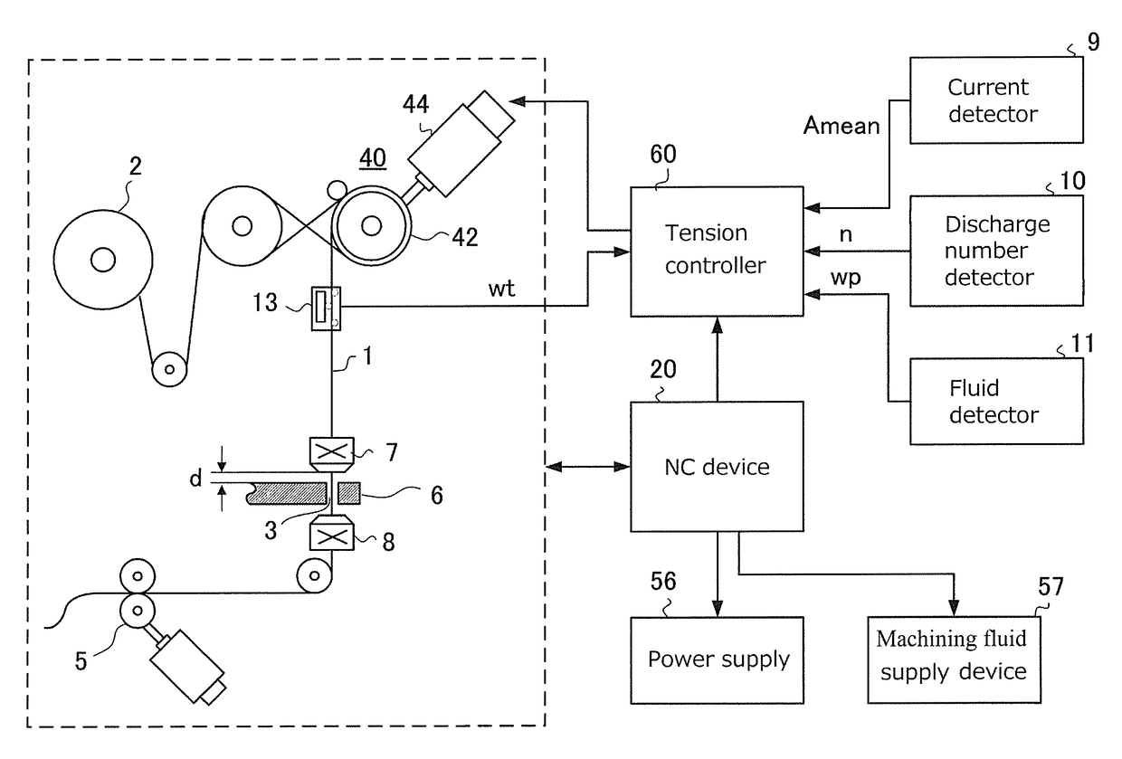
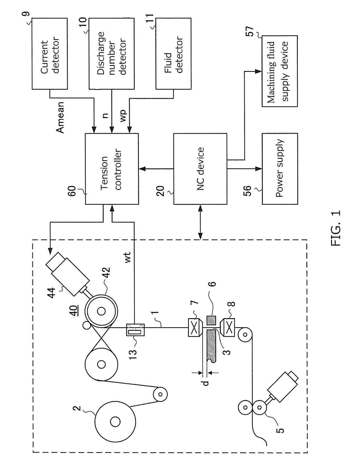
[0022]Referring to FIG. 1, a wire electrical discharge machining device of the present invention is described. A wire electrode 1 is transported from a wire reel 2 to a pulling device 5 via a wire transportation path. A tension applying device 40, a tension detector 13, a pair of nozzles 7, 8 and a plurality of pulleys are located on the wire transportation path. The tension applying device 40 applies a tension for maintaining a straightness of the wire electrode 1 to the wire electrode 1. The tension applying device 40 includes a break pulley 42 to provide a friction to the wire electrode 1 and a servomotor 44 connected to the break pulley 42. The tension detector 13 comprises, for example, a strain gauge, and located between the break pulley 42 and the upper side nozzle 7.

[0023]The nozzles 7, 8 for injecting a machining fluid to a work 6 are located above and below with the work 6 therebetween. A machining gap 3 is formed between the wire electrode 1 and the work 6. In high-speed ...


PUM

PropertyMeasurementUnit
timeaaaaaaaaaa
tensionaaaaaaaaaa
breaking tensionaaaaaaaaaa

Abstract

Provided is a wire electrical discharge machining device which has a tension controller for maintaining the tension of a traveling wire electrode at a tension. The tension controller includes: an allowed tension calculation module for determining an allowed tension that is less than a wire breaking tension at which the wire electrode breaks; and a set tension generation module for generating the set tension in accordance with the allowed tension. When the set tension is greater than the allowed tension, the set tension generation module reduces the set tension. When the set tension is less than the allowed tension, the set tension generation module increases the set tension in such a way that the set tension does not exceed the allowed tension.

Description

CROSS-REFERENCE TO RELATED APPLICATION[0001]This application is a 371 application of an international PCT application serial no. PCT / JP2011 / 074076, filed on Oct. 19, 2011, which claims the priority benefit of Japan application no. 2010-234340, filed on Oct. 19, 2010. The entirety of each of the above-mentioned patent applications is hereby incorporated by reference herein and made a part of this specification.TECHNICAL FIELD[0002]The present invention relates to a wire electrical discharge machining device for machining a work by generating electrical discharge in a gap (“machining gap”) formed between a wire electrode and the work. In particular, the present invention relates to a wire electrical discharge machining device for controlling a tension applied to a wire electrode traveling along a wire transportation path.BACKGROUND TECHNIQUE[0003]In general, during machining, a wire electrode is transported between a pair of wire guides in a direction substantially vertical to XY plan...

Claims


Application Information

Patent Timeline
Patent Type & Authority Patents(United States)
IPC IPC(8): B23H7/10B23H1/02
CPCB23H7/104B23H1/02
Inventor YAMADA, KUNIHARUKOUGO, MASAKIYANAGISAWA, TOMOYUKI
Owner SODICK CO LTD
Why Eureka
Try Eureka