Semiconductor device and method for manufacturing same

a technology of semiconductor devices and semiconductors, applied in the direction of semiconductor devices, basic electric elements, electrical appliances, etc., can solve the problems of difficulty in achieving enhancement types, and achieve the effect of reducing contact resistance and sheet resistan

Active Publication Date: 2017-12-05
PANASONIC INTELLECTUAL PROPERTY MANAGEMENT CO LTD
View PDF10 Cites 1 Cited by
  • Summary
  • Abstract
  • Description
  • Claims
  • Application Information

AI Technical Summary

Benefits of technology

[0018]AlGaN barrier layer 902 including Mg is changed into a p-type, which causes increase in contact resistance and sheet resistance. An Al-based material such as Ti / Al which is widely used in source electrode 903 and drain electrode 904 is a metallic material with a small work function for an n-type GaN-based nitride semiconductor. Thus, when AlGaN barrier layer 902 is changed into the p-type, the contact resistance increases. Further, when AlGaN barrier layer 902 is changed into the p-type, since a carrier density of a two-dimensional electron gas is reduced compared with an i-type (intrinsic type) or an n-type, the sheet resistance increases.
[0020]In order to solve the above problems, an object of the present disclosure is to provide a semiconductor device and a method for manufacturing the same capable of reducing contact resistance and sheet resistance.
[0022]According to this configuration, since the third semiconductor layer is present between the second semiconductor layer which is a barrier layer of the semiconductor device and the fourth semiconductor layer having the p-type conductivity, even when a p-type dopant is diffused during growth of the fourth semiconductor layer, it is possible to reduce the amount of the p-type dopant diffused to the second semiconductor layer. Thus, it is possible to suppress the change of the second semiconductor layer into the p-type, and to suppress deterioration of contact resistance and sheet resistance.
[0024]According to this method, it is possible to manufacture a semiconductor device capable of reducing contact resistance and sheet resistance.
[0025]According to the semiconductor device of the present disclosure, it is possible to reduce contact resistance and sheet resistance.

Problems solved by technology

Accordingly, it is difficult to achieve a characteristic of an enhancement type (normally-off type).

Method used


Image

  • Semiconductor device and method for manufacturing same
  • Semiconductor device and method for manufacturing same
  • Semiconductor device and method for manufacturing same

Examples


first exemplary embodiment

Modification Example 5 of First Exemplary Embodiment

[0108]Next, Modification Example 5 of the first exemplary embodiment will be described. A nitride semiconductor device according to this modification example is an example of a semiconductor device, and is approximately the same as nitride semiconductor device 100 according to the first exemplary embodiment, but is different therefrom in the following points. That is, a diffusion suppression layer has a stacked structure of a semiconductor layer represented as n-type AluGa1-uN (u=0.03) and a semiconductor layer represented as undoped AlaGa1-aN.

[0109]FIG. 10 is a sectional view illustrating a configuration of nitride semiconductor device 190 according to Modification Example 5 of the first exemplary embodiment.

[0110]Nitride semiconductor device 190 according to this modification example has a structure in which diffusion suppression layer 105 represented as IntAluGa1-t-uN (t=0.05 and u=0.05) in nitride semiconductor device 100 accor...

second exemplary embodiment

[0121]Hereinafter, a second exemplary embodiment will be described with reference to FIG. 11. A nitride semiconductor device according to this exemplary embodiment is an example of a semiconductor device, and is approximately the same as nitride semiconductor device 100 according to the first exemplary embodiment, but is different therefrom in that a cap layer formed on barrier layer 104 is provided. In the respective exemplary embodiments described below, the same reference numerals are given to substantially the same components as in the first exemplary embodiment, and description thereof may be omitted.

[0122]FIG. 11 is a sectional view illustrating a configuration of nitride semiconductor device 200 according to the second exemplary embodiment of the present disclosure.

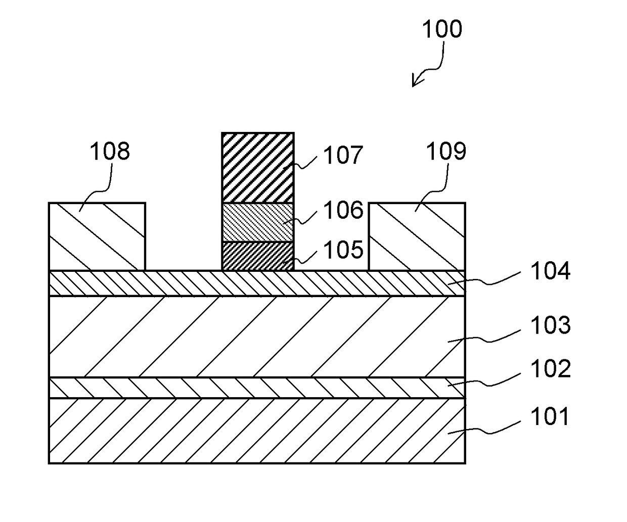
[0123]Nitride semiconductor device 200 includes Si substrate 101 in which a (111) plane is a main plane, for example, buffer layer 102 made of AlN provided on the (111) plane of Si substrate 101, channel layer 103 ...

third exemplary embodiment

[0131]Next, a third exemplary embodiment will be described with reference to FIG. 12. A nitride semiconductor device according to this exemplary embodiment is an example of a semiconductor device, and is approximately the same as nitride semiconductor device 100 according to the first exemplary embodiment, but is different therefrom in the following point. That is, a p-type conductive layer made of p-type AlGaN formed between diffusion suppression layer 105 and p-type conductive layer 106 is provided.

[0132]FIG. 12 is a sectional view illustrating a configuration of nitride semiconductor device 300 according to the third exemplary embodiment of the present disclosure.

[0133]Nitride semiconductor device 300 includes Si substrate 101 in which a (111) plane is a main plane, for example, buffer layer 102 made of AlN provided on the (111) plane of Si substrate 101, channel layer 103 represented as InpAlqGa1-p-qN (p=0.05 and q=0.02) provided on buffer layer 102, barrier layer 104 represente...


PUM


Abstract

A semiconductor device includes: a channel layer which is made of InpAlqGa1-p-qN (0≦p+q≦1, 0≦p, and 0≦q); a barrier layer which is formed on the channel layer and is made of InrAlsGa1-r-sN (0≦r+s≦1, 0≦r) having a bandgap larger than that of the channel layer; a diffusion suppression layer which is selectively formed on the barrier layer and is made of IntAluGa1-t-uN (0≦t+u≦1, 0≦t, and s>u); a p-type conductive layer which is formed on the diffusion suppression layer and is made of InxAlyGa1-x-yN (0≦x+y≦1, 0≦x, and 0≦y) having p-type conductivity; and a gate electrode which is formed on the p-type conductive layer.

Description

BACKGROUND OF THE INVENTION[0001]1. Field of the Invention[0002]The present disclosure relates to a semiconductor device and a method for manufacturing the same.[0003]2. Description of the Related Art[0004]In recent years, researches for a field effect transistor (FET) using a gallium nitride (GaN)-based compound semiconductor material have been actively performed as a power device.[0005]Since a nitride semiconductor material such as GaN can be used for manufacturing various mixed crystals such as aluminum nitride (AlN) and indium nitride (InN), heterojunction can be formed similar to an arsenic semiconductor material such as gallium arsenide (GaAs) in the related art. Particularly, in the heterojunction due to the nitride semiconductor, even in an undoped state, high concentration carriers generated by spontaneous polarization or piezoelectric polarization are generated on an interface of the heterojunction. As a result, in a case where FET is manufactured, the FET is easily formed...

Claims


Application Information

Patent Timeline
Patent Type & Authority Patents(United States)
IPC IPC(8): H01L29/06H01L29/43H01L29/10H01L29/778H01L29/66H01L29/205H01L29/808H01L29/201H01L29/20
CPCH01L29/205H01L29/1066H01L29/432H01L29/66462H01L29/66924H01L29/7786H01L29/8086H01L29/66916H01L29/2003H01L29/201
Inventor KINOSHITA, YUSUKETAMURA, SATOSHIUEDA, TETSUZO
Owner PANASONIC INTELLECTUAL PROPERTY MANAGEMENT CO LTD
Why Eureka
Try Eureka