Electromechanical flywheel with evacuation system

a technology of electric motor and evacuation system, applied in the field of electric motor with evacuation system, can solve the problems that prior art vacuum system generally fails to establish and maintain desired vacuum conditions, and achieve the effect of limiting temperature ris

Active Publication Date: 2017-12-12
ROTONIX CHINA CO LTD
View PDF51 Cites 9 Cited by
  • Summary
  • Abstract
  • Description
  • Claims
  • Application Information

AI Technical Summary

Benefits of technology

[0009]In an embodiment, an electromechanical flywheel method of configuring rotating parts that is enabled by a variable geometry drag pump, the method comprising the steps of providing a flywheel mass made from a carbon composite; providing a rotor made from a metal; encircling the rotor with the mass; engaging the rotor and the mass via an interference fit therebetween; providing a variable geometry planar drag pump with a drag pump gap between a labyrinth ring and an end of the flywheel mass; and, during variable speed operation of the flywheel mass in an evacuated space, controlling the drag pump gap to limit the temperature rise of the flywheel mass.

Problems solved by technology

However, prior art vacuum systems have generally failed to establish and maintain desired vacuum conditions.

Method used


Image

  • Electromechanical flywheel with evacuation system
  • Electromechanical flywheel with evacuation system
  • Electromechanical flywheel with evacuation system

Examples


Embodiment Construction

[0027]The disclosure provided in the following pages describes examples of some embodiments of the invention. The designs, figures, and descriptions are non-limiting examples of certain embodiments of the invention. For example, other embodiments of the disclosed device may or may not include the features described herein. Moreover, disclosed advantages and benefits may apply to only certain embodiments of the invention and should not be used to limit the disclosed inventions.

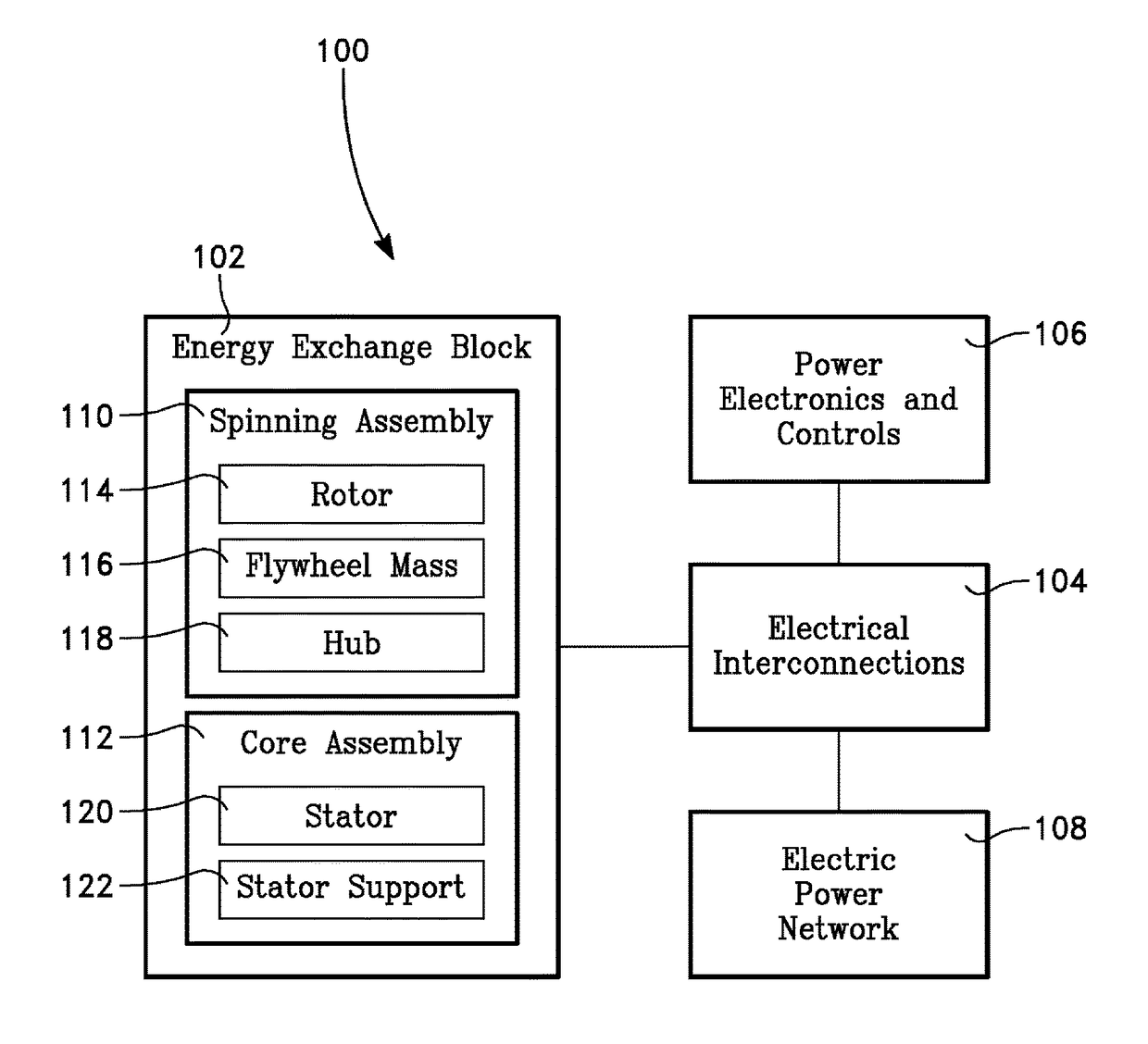
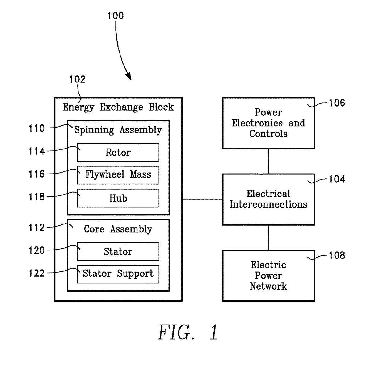
[0028]FIG. 1 shows an electromechanical flywheel machine 100. Electrical interconnections 104 electrically couple an energy exchange block 102, power electronics and controls 106, and an electric power network 108.

[0029]As used herein, unless otherwise stated, the term coupled refers to a direct or indirect connection such as 1) A connected directly to B and 2) C connected indirectly to E via D.

[0030]The energy exchange block 102 includes a spinning assembly 110 and a core assembly 112. The spinning assembly in...


PUM


Abstract

An electromechanical flywheel machine includes a flywheel mass enclosed in an evacuable housing.

Description

PRIORITY CLAIM AND INCORPORATION BY REFERENCE[0001]This application is a continuation-in-part of U.S. patent application Ser. No. 13 / 849,484 filed Mar. 23, 2013 which claims the benefit of U.S. Prov. Pat. App. No. 61 / 615,860 filed Mar. 26, 2012.[0002]This application incorporates by reference, in their entireties and for all purposes: 1) U.S. patent application Ser. No. 13 / 849,484 filed Mar. 13, 2013, 2) U.S. Prov. Pat. App. No. 61 / 615,860 filed Mar. 26, 2012; 3) U.S. Pat. No. 6,884,039 to Woodard et al. filed Dec. 30, 2002; and 4) U.S. Pat. No. 6,175,172 to Bakholdin et al. filed Aug. 4, 1997.BACKGROUND OF THE INVENTION[0003]Known flywheels store kinetic energy, that is, the energy of motion. When called upon to release this energy, the flywheel slows as kinetic energy is depleted. Flywheels driving and driven by electric machines are also know. For decades, such electromechanical machines have been built and have achieved varying degrees of operational success. Widespread applicat...

Claims


Application Information

Patent Timeline
Patent Type & Authority Patents(United States)
IPC IPC(8): H02K7/02F16F15/315
CPCH02K7/02F16F15/315H02K7/025Y02E60/16H02K2205/12
Inventor KALEV, CLAUDE MICHAELROSEN, ROBERT A.
Owner ROTONIX CHINA CO LTD
Why Eureka
Try Eureka