Energy control system, energy control device, and energy control method for prioritizing a power generation source based on the possibility of selling generated power

a technology of energy control system and energy control device, which is applied in the direction of computer control, process and machine control, instruments, etc., can solve the problems of inconvenient loss of power to the grid in this way, inability to apply the cost of fuel cell fuel, and inability to sell power to the grid. , to achieve the effect of economic operation

Active Publication Date: 2017-12-19
KYOCERA CORP
View PDF16 Cites 3 Cited by
  • Summary
  • Abstract
  • Description
  • Claims
  • Application Information

AI Technical Summary

Benefits of technology

[0013]Accordingly, the present invention has been conceived in light of the above circumstances and provides an energy control system, energy control device, and energy control method capable of economical operation not only when sale of power generated by photovoltaic power generation is possible, but also when the sale of power is not possible.
[0024]According to the present invention, it is possible to provide an energy control system, energy control device, and energy control method capable of economical operation not only when sale of power generated by photovoltaic power generation is possible, but also when the sale of power is not possible.

Problems solved by technology

It might not be possible, however, to sell the above-described power generated by photovoltaic power generation to the grid.
During the above-described operation, i.e. the operation to use both fuel cell power generation and photovoltaic power generation, losing the ability to sell power to the grid in this way is inconvenient.
First of all, if power generated by photovoltaic power generation cannot be sold, the payment for sold power cannot be applied to the cost of fuel for the fuel cell.
Furthermore, power that is generated by photovoltaic power generation but that cannot be sold may be wasted.
Even by doing so, however, there is still a risk that the power after the secondary cell becomes fully charged will be wasted.
Such operation is far from economical.

Method used


Image

  • Energy control system, energy control device, and energy control method for prioritizing a power generation source based on the possibility of selling generated power
  • Energy control system, energy control device, and energy control method for prioritizing a power generation source based on the possibility of selling generated power
  • Energy control system, energy control device, and energy control method for prioritizing a power generation source based on the possibility of selling generated power

Examples


Embodiment Construction

[0032]The following describes an embodiment of the present invention with reference to the drawings.

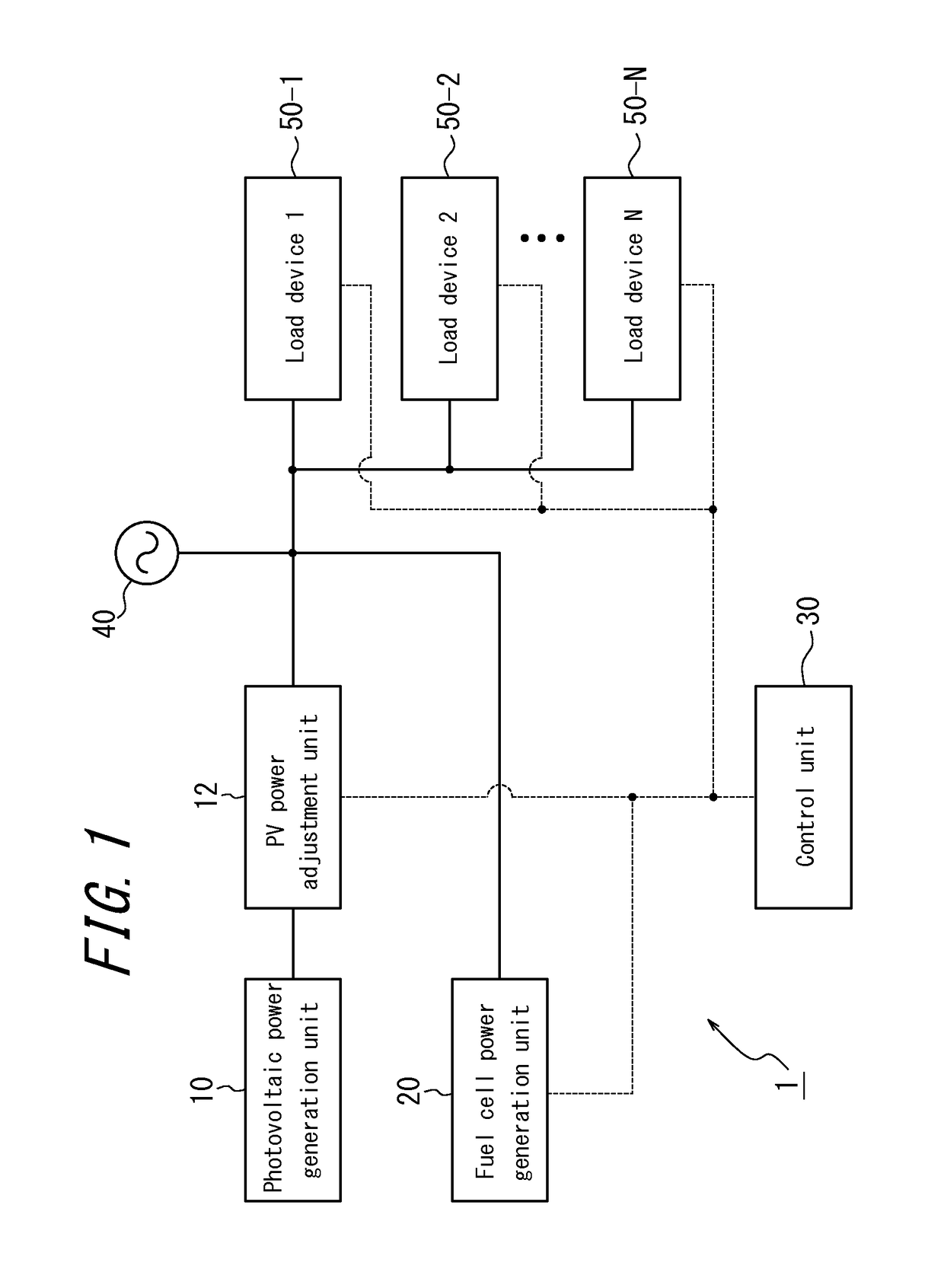
[0033]FIG. 1 schematically illustrates an exemplary structure of an energy control system according to an embodiment of the present invention.

[0034]As illustrated in FIG. 1, an energy control system 1 according to the present embodiment includes a photovoltaic power generation unit 10, a PV power adjustment unit 12, a fuel cell power generation unit 20, and a control unit 30. In FIG. 1, control lines indicating the exchange of control signals between functional units are represented with dashed lines, whereas the power lines indicating the flow of power between functional units are represented with solid lines. Each control line may be wired or wireless. Furthermore, each control line may use a protocol unique to the manufacturer, yet signal transmission and reception preferably conforms to a standard protocol such as ECHONET Lite or ZigBee (trademark).

[0035]The photovoltaic power gen...


PUM


Abstract

An energy control system (1) includes a photovoltaic power generation unit (10) that is connected to the grid and generates power using sunlight, a gas power generation unit (20) that generates power using gas, and a control unit (40) that performs control to supply a load by prioritizing the power generated by the gas power generation unit (20) when sale of the power generated by the photovoltaic power generation unit (10) to the grid is possible and to supply the load by prioritizing the power generated by the photovoltaic power generation unit (10) when the sale is not possible.

Description

CROSS-REFERENCE TO RELATED APPLICATION[0001]This application claims priority to and the benefit of Japanese Patent Application No. 2011-212973 filed Sep. 28, 2011, the entire contents of which are incorporated herein by reference.TECHNICAL FIELD[0002]The present invention relates to an energy control system, energy control device, and energy control method. In particular, the present invention relates to an energy control system, energy control device, and energy control method for controlling power generated by a photovoltaic power generation unit and a gas power generation unit.BACKGROUND[0003]Fuel cells are a known way of converting the energy of fuel directly into electrical energy. A typical structure for a fuel cell includes a pair of porous electrodes, i.e. a fuel electrode and an air electrode, with an electrolyte layer therebetween. The fuel electrode is in contact with hydrogen, and the air electrode is in contact with oxygen. A fuel cell with such a structure generates po...

Claims


Application Information

Patent Timeline
Patent Type & Authority Patents(United States)
IPC IPC(8): G05B15/02H02J1/14H02J3/00H02J3/14H02J3/38
CPCG05B15/02H02J1/14H02J3/14H02J3/383H02J3/008Y02E10/563H02J2300/24H02J3/381Y02E10/56H02J2310/64
Inventor IWATA, KEI
Owner KYOCERA CORP
Why Eureka
Try Eureka