
Apparatus, system, and method of storage and retrieval of local volatile memory content of non-volatile storage memory

a volatile memory and content technology, applied in the field of data recovery systems for memory devices, can solve the problems of increased power consumption, increased power consumption, and loss of volatile memory content stored in non-volatile storage units, so as to reduce the overall required power, thermal and cost of the non-volatile storage unit, and reduce the latency of safely storing.

Active Publication Date: 2017-12-19
EXECUTIVE ADVISORY FIRM LLC
View PDF5 Cites 5 Cited by
  • Summary
  • Abstract
  • Description
  • Claims
  • Application Information

AI Technical Summary

Benefits of technology

[0016]The inventive method, system and apparatus drastically reduce the latency of safely storing the content of the volatile memory block within the non-volatile storage controller during unpredictable, unscheduled power loss. They will also reduce the required power hold-up circuitry for either battery or super capacitor, will reduce overall required power, thermal, and cost of the non-volatile storage unit.

Problems solved by technology

If the non-volatile storage unit does not have a power back-up circuitry while the system experience unpredicted, unscheduled power loss, the content stored in the volatile memory within non-volatile storage unit will be lost and unrecoverable.
The larger the volatile memory block size, the higher power consumption is required to safely and permanently store the content stored in the volatile memory block in the non-volatile storage unit.
The increase of power consumption translate to a larger battery or capacitor block to be incorporated into the non-volatile battery unit, which in turn requires large enough additional real state on the non-volatile storage unit, additional power requirements for charging and maintenance of the power holding blocks, additional thermal (i.e., heat dissipation) requirement for the large battery or super capacitor, and additional cost.

Method used


Image

  • Apparatus, system, and method of storage and retrieval of local volatile memory content of non-volatile storage memory
  • Apparatus, system, and method of storage and retrieval of local volatile memory content of non-volatile storage memory
  • Apparatus, system, and method of storage and retrieval of local volatile memory content of non-volatile storage memory

Examples


Embodiment Construction

[0030]As used in the description herein and throughout the claims that follow, the meaning of “a,”“an,” and “the” includes plural reference unless the context clearly dictates otherwise. Also, as used in the description herein, the meaning of “in” includes “in” and “on” unless the context clearly dictates otherwise.

[0031]As used herein, and unless the context dictates otherwise, the term “coupled to” is intended to include both direct coupling (in which two elements that are coupled to each other contact each other) and indirect coupling (in which at least one additional element is located between the two elements). Therefore, the terms “coupled to” and “coupled with” are used synonymously. As used herein, the term “operatively coupled to” refers to electronic components that are coupled with one another such that an electronic communication path exists between one electronic hardware component and another electronic hardware component.

[0032]Groupings of alternative elements or embo...


PUM


Abstract

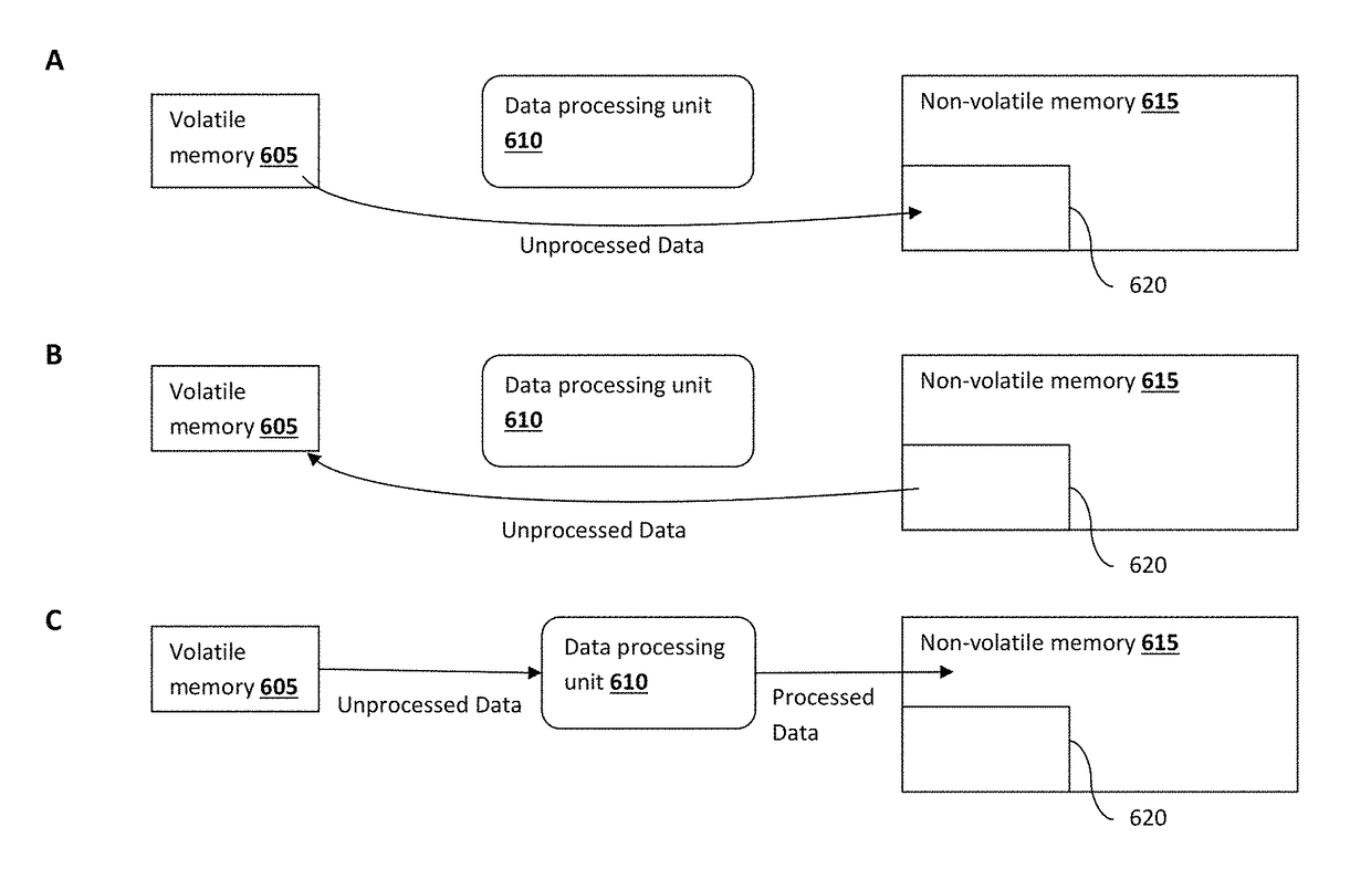
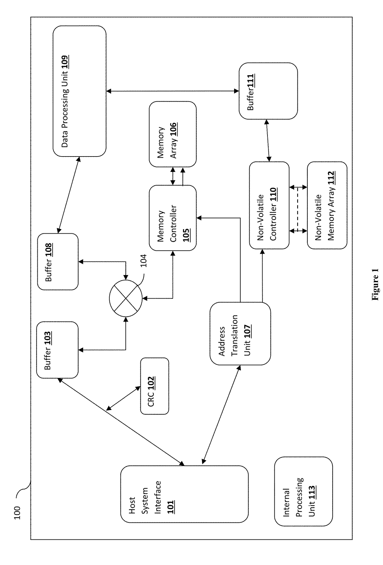
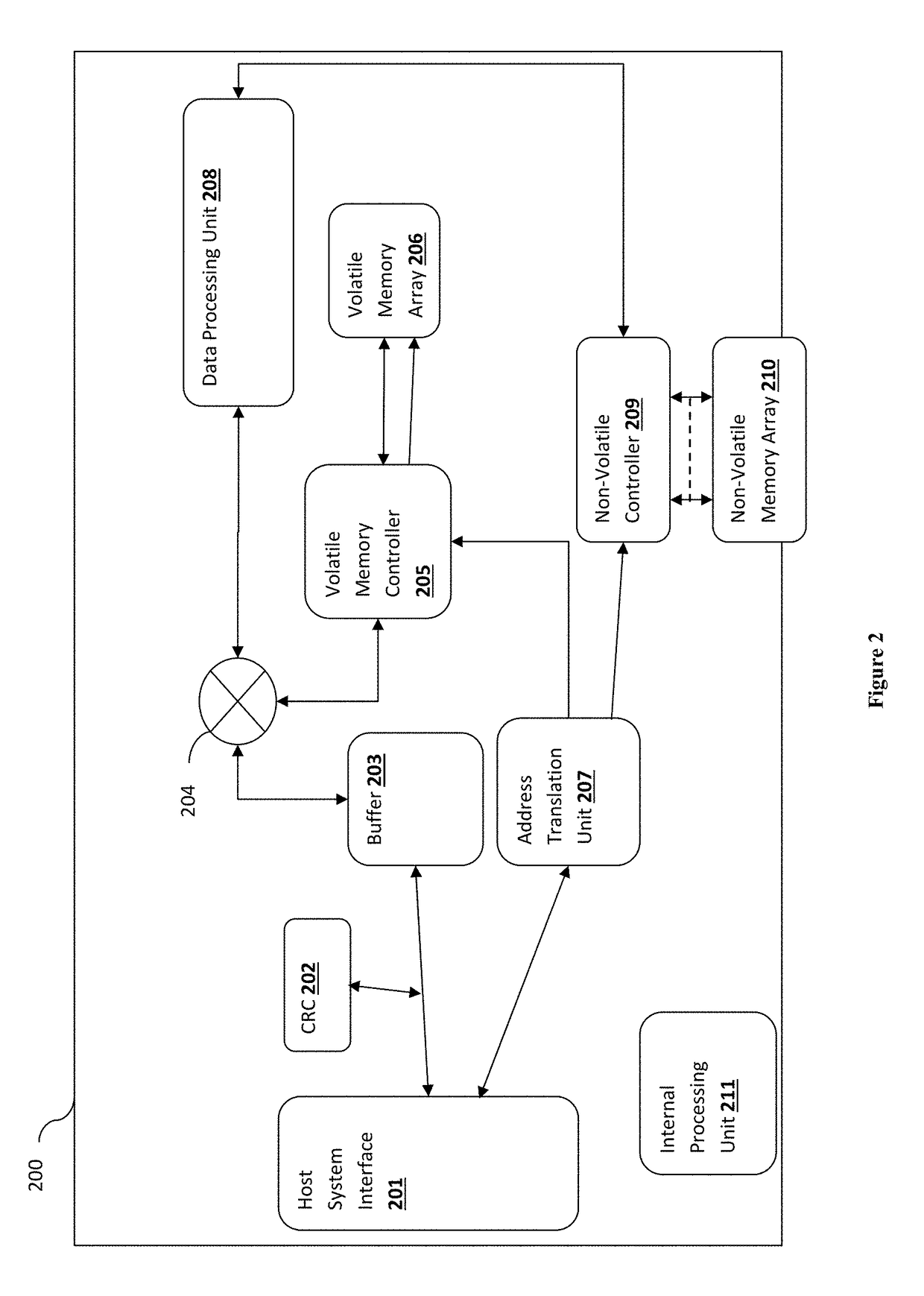
A system, method and apparatus to provide data recovery capabilities during an emergency power failure event. A non-volatile storage system is provided to be coupled with a host computer system. The non-volatile storage system includes an embedded non-volatile memory array for persistently storing data and an embedded volatile memory array for temporarily storing the data before committing the data to the non-volatile memory array. The non-volatile storage system provides a normal operating data path transferring data from the volatile memory array to the non-volatile memory array during normal operating condition. The normal operating data path includes data processing blocks. The non-volatile storage system also provides an emergency data path for transferring data from the volatile memory array to the non-volatile memory array during an emergency power loss condition. The emergency data path excludes the data processing blocks.

Description

[0001]This application claims the benefit of priority to U.S. provisional application 62 / 184,200 filed on Jun. 24, 2015. This and all other extrinsic references referenced herein are incorporated by reference in their entirety.FIELD OF THE INVENTION[0002]The field of the invention is data recovery systems for memory devicesBACKGROUND[0003]The background description includes information that may be useful in understanding the present invention. It is not an admission that any of the information provided herein is prior art or relevant to the presently claimed invention, or that any publication specifically or implicitly referenced is prior art.[0004]All publications herein are incorporated by reference to the same extent as if each individual publication or patent application were specifically and individually indicated to be incorporated by reference. Where a definition or use of a term in an incorporated reference is inconsistent or contrary to the definition of that term provided ...

Claims


Application Information

Patent Timeline
Patent Type & Authority Patents(United States)
IPC IPC(8): G06F1/30G06F11/16G06F3/06G11C11/00
CPCG06F1/30G06F3/064G06F3/0619G06F3/0631G06F3/0685G06F11/1662G06F3/0647G11C11/005G06F2201/805G06F3/0632G06F3/0688G06F11/1441G06F11/14
Inventor AMIDI, MIKE HOSSEIN
Owner EXECUTIVE ADVISORY FIRM LLC
Learn More