Bearing assembly with lubrication cartridge

a technology of lubricating cartridges and bearings, which is applied in the direction of bearings, shafts and bearings, rotary bearings, etc., can solve the problems of sharp rise in bearing temperature and bearing temperature drop, and achieve the effects of stimulating thermal bleeding and oil release from the cartridge, facilitating heat transfer, and large surface area

Active Publication Date: 2017-12-26
AB SKF
View PDF9 Cites 3 Cited by
  • Summary
  • Abstract
  • Description
  • Claims
  • Application Information

AI Technical Summary

Benefits of technology

[0010]The honeycomb structure provides a large surface area for the grease to adhere to, meaning that grease can be retained within the cartridge for a long period. A further advantage of the large surface area is that heat transfer is facilitated. When an oil film that lubricates rolling contact surfaces within the bearing becomes too thin to separate the surfaces, asperity contact takes place, leading to friction and a sharp rise in bearing temperature. In a grease cartridge according to the invention, the temperature rise is quickly transferred from the honeycomb structure to the grease, thereby stimulating thermal bleeding and oil release from the cartridge. The released oil replenishes the oil film, causing bearing temperature to fall. The grease in the axial passageways of the honeycomb structure quickly returns to “normal” temperature and the thermal bleed rate drops correspondingly.
[0011]The grease cartridge therefore not only provides a long-lasting grease reservoir in a bearing assembly according to the invention, but is also thermally responsive such that additional lubrication can be provided when it is needed most. In a preferred embodiment, the honeycomb structure and further parts of the cartridge are formed from a metallic material such as aluminum, to enhance the thermal responsiveness of the cartridge
[0016]In one embodiment, the grease cartridge is formed from the honeycomb structure. The structure may comprise several passageways which are radially stacked and whereby each passageway is open at both axial ends. Alternatively, to reduce the amount of lubricant that is released, some of the openings may be closed off towards the first and second bearing cavities. The cartridge then suitably comprises a number of channels that are e.g. drilled though the honeycomb structure, such that passageways which are closed off towards the first and second cavities are in communication with passageways that are open towards the first and second cavities.
[0023]Thus, a grease cartridge comprising a honeycomb structure may be used in a variety of ways, so as to improve bearing lubrication and prolong grease life within the bearing. Other advantages will become apparent from the detailed description and accompanying drawings.

Problems solved by technology

When an oil film that lubricates rolling contact surfaces within the bearing becomes too thin to separate the surfaces, asperity contact takes place, leading to friction and a sharp rise in bearing temperature.
The released oil replenishes the oil film, causing bearing temperature to fall.

Method used


Image

  • Bearing assembly with lubrication cartridge
  • Bearing assembly with lubrication cartridge
  • Bearing assembly with lubrication cartridge

Examples


Embodiment Construction

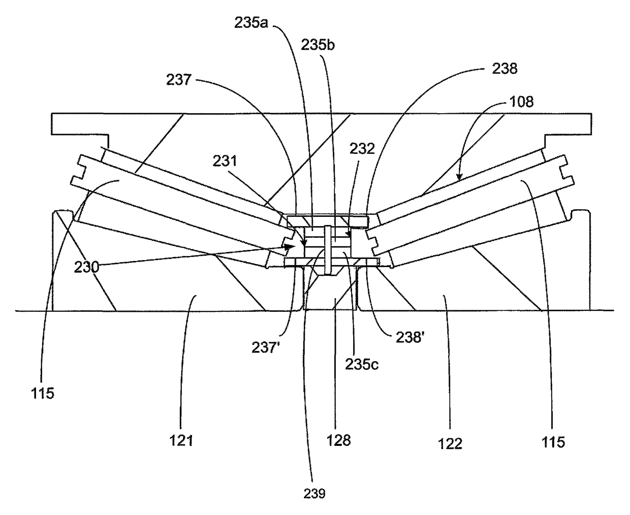
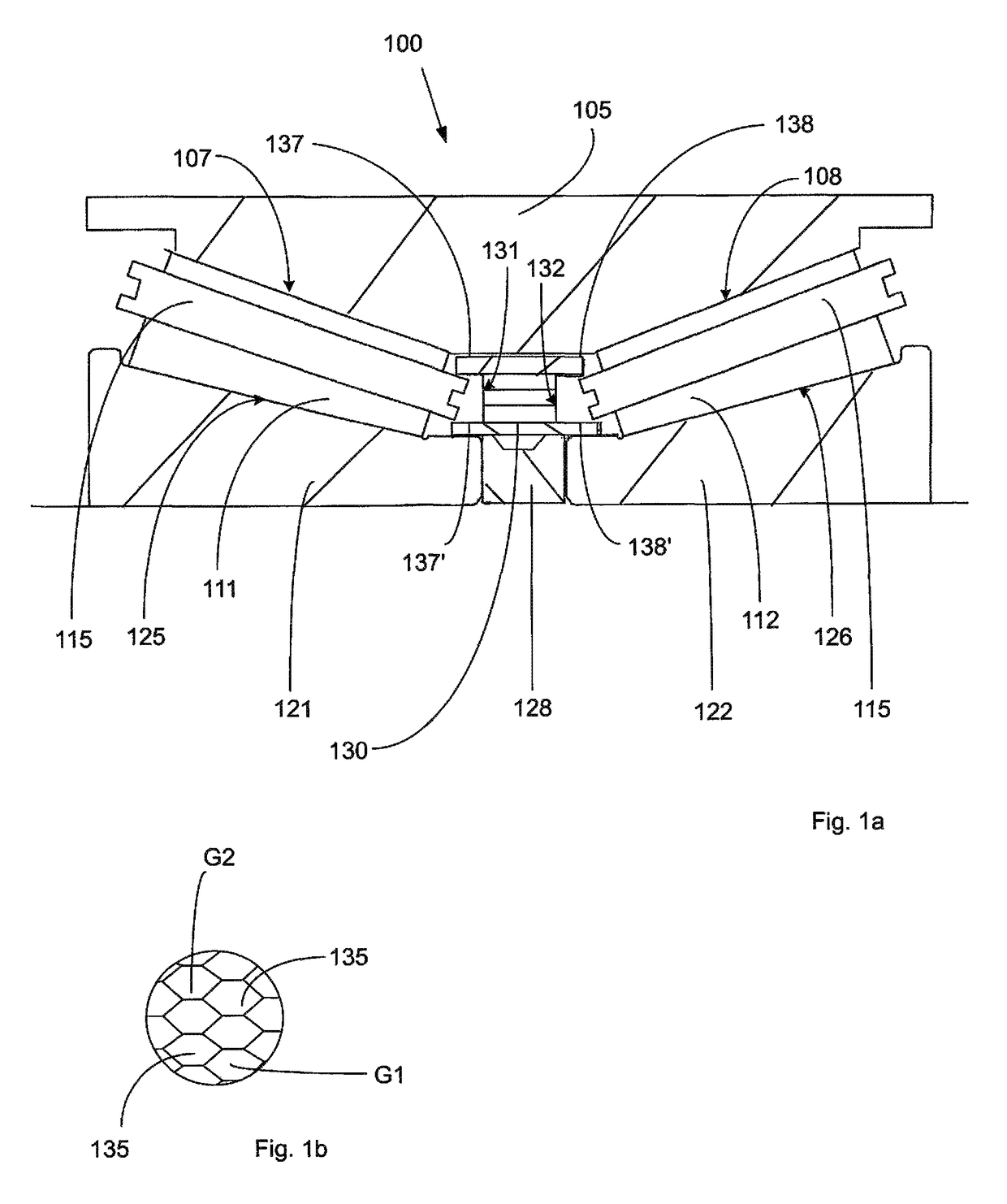
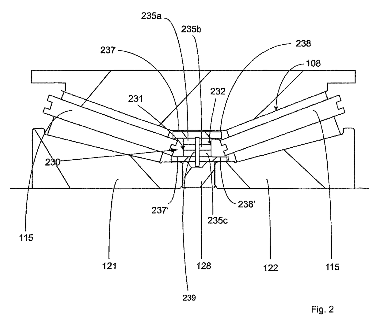
[0031]An example of a first embodiment of a bearing assembly according to the invention is shown in FIG. 1a. The bearing assembly 100 comprises a double-row taper roller bearing having an outer ring 105 with a first outer raceway 107 for a first set of tapered rollers 111 and a second outer raceway 108 for a second set of tapered rollers 112. Each of the first and second sets of rollers 111, 112 is retained by a cage 115, and the bearing further comprises a first inner ring 121 and a second inner ring 122 having first and second inner raceways 125, 126. A first bearing cavity is defined between the first inner and outer raceways 125, 107 and a second bearing cavity is defined between the second inner and outer raceways 126, 108. The bearing is adapted for inner ring rotation in this example.

[0032]The bearing is grease lubricated, whereby a suitable bearing grease is provided between the outer ring 105 and the inner rings 121, 122 in a conventional manner. To provide improved, long-l...


PUM


Abstract

A bearing assembly comprising a rolling element bearing having a first row of rolling elements arranged in a first bearing cavity between a first inner raceway and a first outer raceway of the bearing, and having a second row of rolling elements arranged in a second bearing cavity between a second inner raceway and a second outer raceway of the bearing. The assembly further comprises an annular grease cartridge arranged between the first and second rows of rolling elements. The annular grease cartridge is at least partly formed from a honeycomb structure having axially extending passageways filled with a grease lubricant, wherein at least some of passageways are open towards the first and second bearing cavities.

Description

CROSS REFERENCE TO RELATED APPLICATION[0001]This is a U.S. National Stage Application claiming the benefit of International Application No. PCT / EP2013 / 063984 filed on 3 Jul. 2013, which is incorporated herein by reference in its entirety.FIELD OF THE INVENTION[0002]The present invention relates to a bearing assembly comprising a cartridge at least partly filled with a grease lubricant.BACKGROUND TO THE INVENTION[0003]A bearing assembly of this kind is known from U.S. Pat. No. 5,803,616, which discloses a double-row taper roller bearing in which a grease retainer is mounted to an outer ring of the bearing between the two rows of tapered rollers, at a small-diameter end of the rollers. In a tapered roller bearing, grease lubricant is urged from the small diameter end of the bearing to a large-diameter end under the action of centrifugal force. Therefore, grease that is initially provided between the two roller sets may migrate relatively quickly to an axially outer side of the bearing...

Claims


Application Information

Patent Timeline
Patent Type & Authority Patents(United States)
IPC IPC(8): F16C19/00F16C33/66F16C19/52F16C19/18F16C19/38
CPCF16C33/6622F16C19/522F16C19/525F16C33/6611F16C33/6633F16C33/6648F16C33/6625F16C19/386F16C19/184
Inventor HOLSNIJDERS, JOSMARTINETTI, MAURIZIOROSENGREN, FILIP
Owner AB SKF
Why Eureka
Try Eureka