Full flat mirror guiding reflections to aperture of panoramic optical device

Inactive Publication Date: 2018-01-02
HOYOS INTEGRITY CORP
View PDF13 Cites 0 Cited by
  • Summary
  • Abstract
  • Description
  • Claims
  • Application Information

AI Technical Summary

Benefits of technology

The present invention describes a camera that has a special optical system called a quadric reflector and a mirror. The cameras can capture a wide-angle image in just one shot. The special shape of the reflector and the position of the mirror help to minimize unwanted reflections and improve image quality. The camera also has special optical elements that focus the light passing through the aperture, allowing for better control over the image. This design helps to produce high-quality images in a simple and efficient way.

Problems solved by technology

Providing high quality optics in a panoramic camera is challenging.
These approaches result in a cumbersome physical configurations and product distorted 360 degree images lacking high fidelity.
The limitation can include image banding which can occur when an environment includes objects such as mirrors and windows which can reflect additional light to optical components.
A “double”“triple” or greater reflection will result in optical noise.
Desired light (that should be reflected from the full flat mirror through the aperture is absorbed by a side wall. FIG. 1L shows a problem that exists when the cavity is not deep enough.
The filtered wavelengths can blur the image and produce color rendering errors in some embodiments.
For example, infrared, violet, and / or ultraviolet wavelengths may be undesired in that they contribute to blurring the image and producing color rendering errors in some embodiments of the disclosure.
These stray reflections would otherwise add noise to the image being captured.
Further recessing will result in blockage of desired reflections (primary ones).

Method used


Image

  • Full flat mirror guiding reflections to aperture of panoramic optical device
  • Full flat mirror guiding reflections to aperture of panoramic optical device
  • Full flat mirror guiding reflections to aperture of panoramic optical device

Examples


embodiment 510

[0057]In embodiment 510, an overhang enclosure 512 can be friction fitted to a base of a panoramic optical device. In the embodiment, a bottom portion of a transparent spacer can be securely fitted against a protruding wall of base 514. For example, enclosure 512 can be mated against a lip (e.g., area 516) of base 514. It should be appreciated that enclosure 512 can be fitted to base 514 using one or more traditional and / or proprietary attachment mechanisms. Attachment mechanisms can include, but is not limited to, snapping / locking mechanism, a screw based attachment mechanism, and the like.

embodiment 540

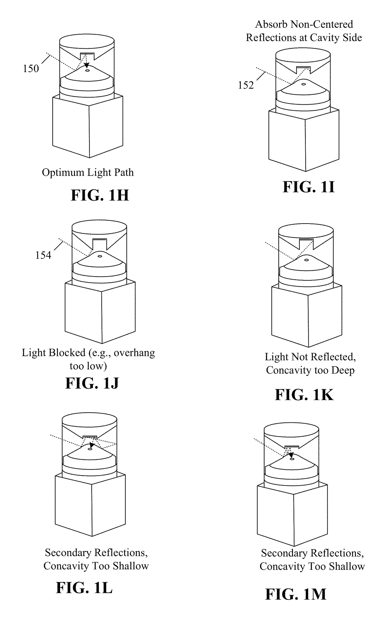
[0058]In embodiment 540, the overhang enclosure 512 can include a conical cross section (e.g., cavity 570) corresponding to dimensions 522, 550 and an overhang 544 with dimension 557 at an angle 556. In one instance, mirror 542 can be recessed within the cavity 570 based on optimum depth 560. In one configuration of the instance, depth 560 can include a cylindrical portion which can recess the mirror 542 for optimum light reflection into aperture of reflector 520. The cavity 570 can be defined by internal angle 554 which can be utilized to control environmental light absorption. That is, angle 554 can be adjusted to ensure optimum light absorption without affecting light reflected from mirror 542 or reflector 520.

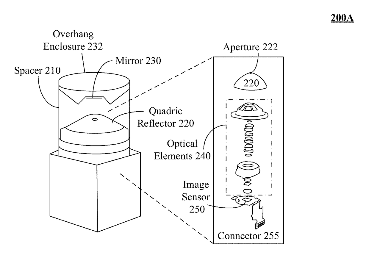
[0059]In one instance, overhang 544 can be defined by angle 556 and length 557 which can approximately conform to an inverted conical pyramid. In one embodiment, overhang enclosure 512 can be positioned at a distance 558 from quadric reflector 520 to enable appropriate envi...


PUM


Abstract

A reflector can have a conical shape. The shape can tapers from a wide base to an apex. The apex can include an aperture, a mirror, and a set of one or more optical elements. A mirror is location in a cavity and is positioned within an overhang enclosure of the device in a plane approximately parallel to a circular cross section of the conical shape. The mirror can reflect environmental light that is reflected by the reflector into the aperture or reflect light emitting from the aperture onto the reflector. Stray light reflected by the mirror is absorbed by the cavity walls. A set of one or more optical elements can be positioned at least partially within a volumetric region of the reflector. The one or more optical elements focus light passing through the aperture to an image sensor.

Description

BACKGROUND[0001]The present invention relates to the field of a single-shot panoramic optical device and, more particularly, to a full flat mirror guiding reflections to an aperture of a panoramic optical device.[0002]Providing high quality optics in a panoramic camera is challenging. Different approaches have been taken for this problem. One approach is to move a lens and to capture a set of images as the lens moves, which cover a field of view over time. The images from the moved lens are combined to form panoramic scene. Another approach is to form an array of multiple different camera lenses and to combine the image results captured by the array of lenses into a single image. Still another is to utilize an ultra-wide angle lens (e.g., a fish-eye lens) to capture a scene with a wider-than-normal field of view. Yet another is to use a panoramic optical device to create a 360 degree horizontal field of view using a single shot (a discrete point of time using a single lens). This la...

Claims


Application Information

Patent Timeline
IPC IPC(8): G02B13/06H04N5/232G02B17/08G02B5/22G03B37/00
CPCG02B13/06G02B17/08H04N5/23238G02B5/22G02B5/208H04N23/55H04N23/60H04N23/698
Inventor DURAZO, PATRICIOPETERSON, GARYROBERTSON, JR., WILLIAM H.SHEMELYNCE, JOHN N.VERMA, AMIT
Owner HOYOS INTEGRITY CORP
Why Eureka
Try Eureka