Sensor device and residual stress detection system employing same

a technology of sensor device and residual stress, which is applied in the direction of measurement device, force measurement, instruments, etc., can solve the problems of inability to realize real-time detection, inability to meet the requirement of on-site measurement, and inability to realize on-site measurement with x-ray diffraction, etc., to achieve enhanced reliability, reduce size, and improve integration

Active Publication Date: 2018-01-09
BEIJING INSTITUTE OF TECHNOLOGYGY
View PDF26 Cites 2 Cited by
  • Summary
  • Abstract
  • Description
  • Claims
  • Application Information

AI Technical Summary

Benefits of technology

[0007]The present invention can realize the function of fast and accurately determining the value of residual stress, as well as rapid and reliable operation.
[0009]This can reduce the contact area between the wedges and the plate as well as errors caused by plate deformation without affecting the energy of ultrasound beams.
[0017]The high frequency date acquisition card with its acquisition frequency of 1 GHz is employed since the stress-induced change of ultrasonic transit time is in nanoseconds. In addition, the ultrasonic transmission card is integrated with the date acquisition card, resulting in a system with a higher degree of integration and enhanced reliability, as well as a more portable industrial personal computer (IPC) with significantly reduced size.
[0018]Preferably a temperature acquisition card is further provided to acquire real-time ambient temperature and eliminate the measurement error of stress due to change of ambient temperature.

Problems solved by technology

Also the process of sticking strain gages is time-consuming so that a real-time detection cannot be achieved.
It is not possible to realize an on-site measurement with X-Ray diffraction due to its harmful radiation to human body, as well as long testing time, even though it has been put on the market.
Although many studies have been carried out on stress measurement by using ultrasound, it cannot meet the requirement of on-site measurement due to unreasonable design of structure, various interfering factors, and poor repeatability.

Method used


Image

  • Sensor device and residual stress detection system employing same
  • Sensor device and residual stress detection system employing same
  • Sensor device and residual stress detection system employing same

Examples


embodiment 1

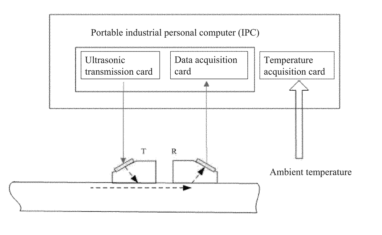
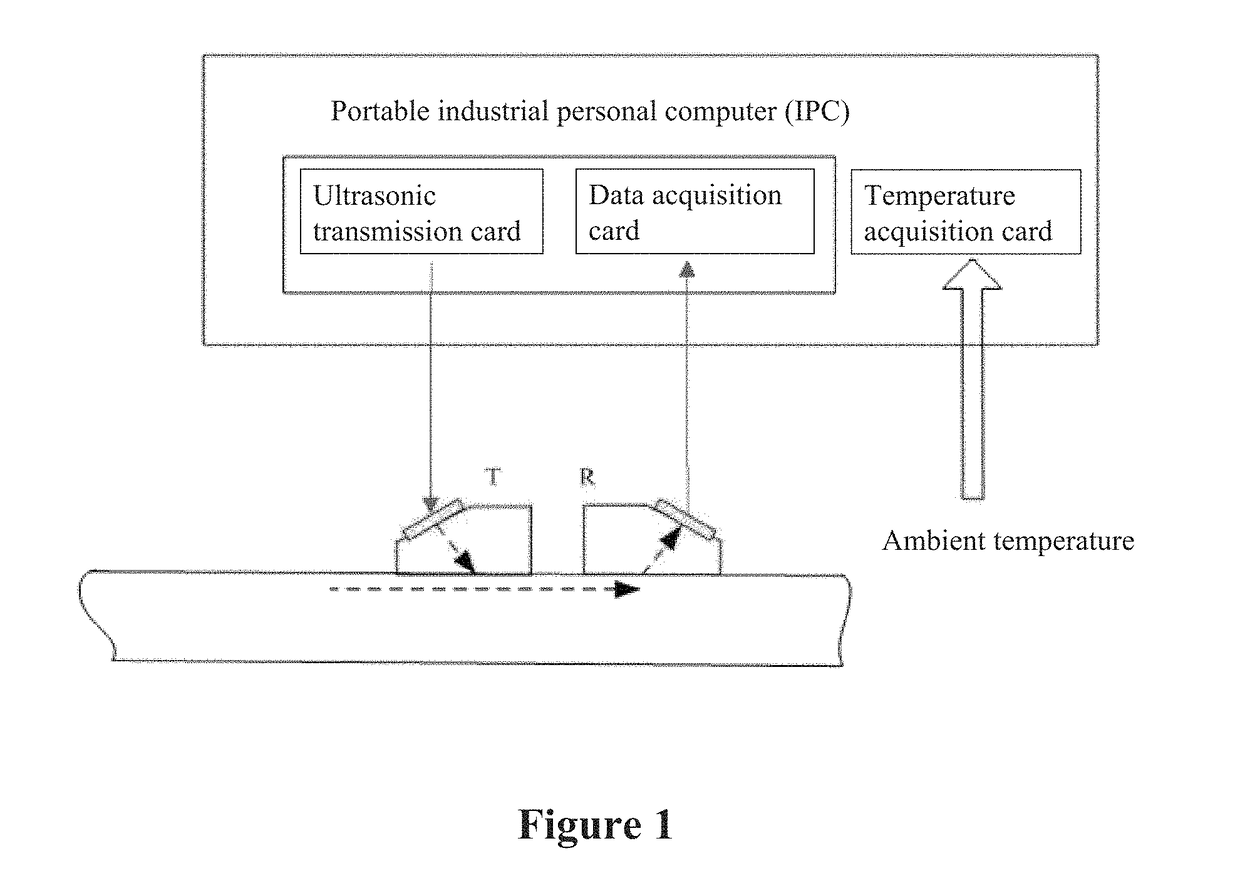
[0033]The near-surface residual stress detection system for metal materials, includes two major parts, that are hardware and software, and auxiliary equipment. As shown in FIG. 1, based on a computer platform, the present invention mainly comprises several parts, such as an exciting and receiving probe, an ultrasonic transmittance card, a data acquisition card, a computer system, a transmission line, etc. When there is a large temperature difference, the plexiglass wedge 5 (sonolucent wedge) and top fixed plate 2 would experience deformation caused by thermal expansion and contraction. A temperature acquisition card is further installed to acquire real-time ambient temperature by software (shown by the hollow arrow in FIG. 1), and eliminate the deformation of mechanical part of the system and effect on sound speed both caused by change of ambient temperature, so that the system can be adapted for measurement under a complex environment and have a wider range of applications. The hig...

embodiment 2

[0043]Sensor device 23 may also employ other configurations. For example, when domestic and foreign designers are designing the configuration of ultrasonic oblique incident sensor, it is common for them to fix the ultrasonic transducer in the plexiglass wedge with bolts or special fixture. While for this configuration, in a case where the transducer is coupled with the wedge, every time the transducer need to be removed and mounted again after coating with the coupling agent, resulting in an increased inconvenience.

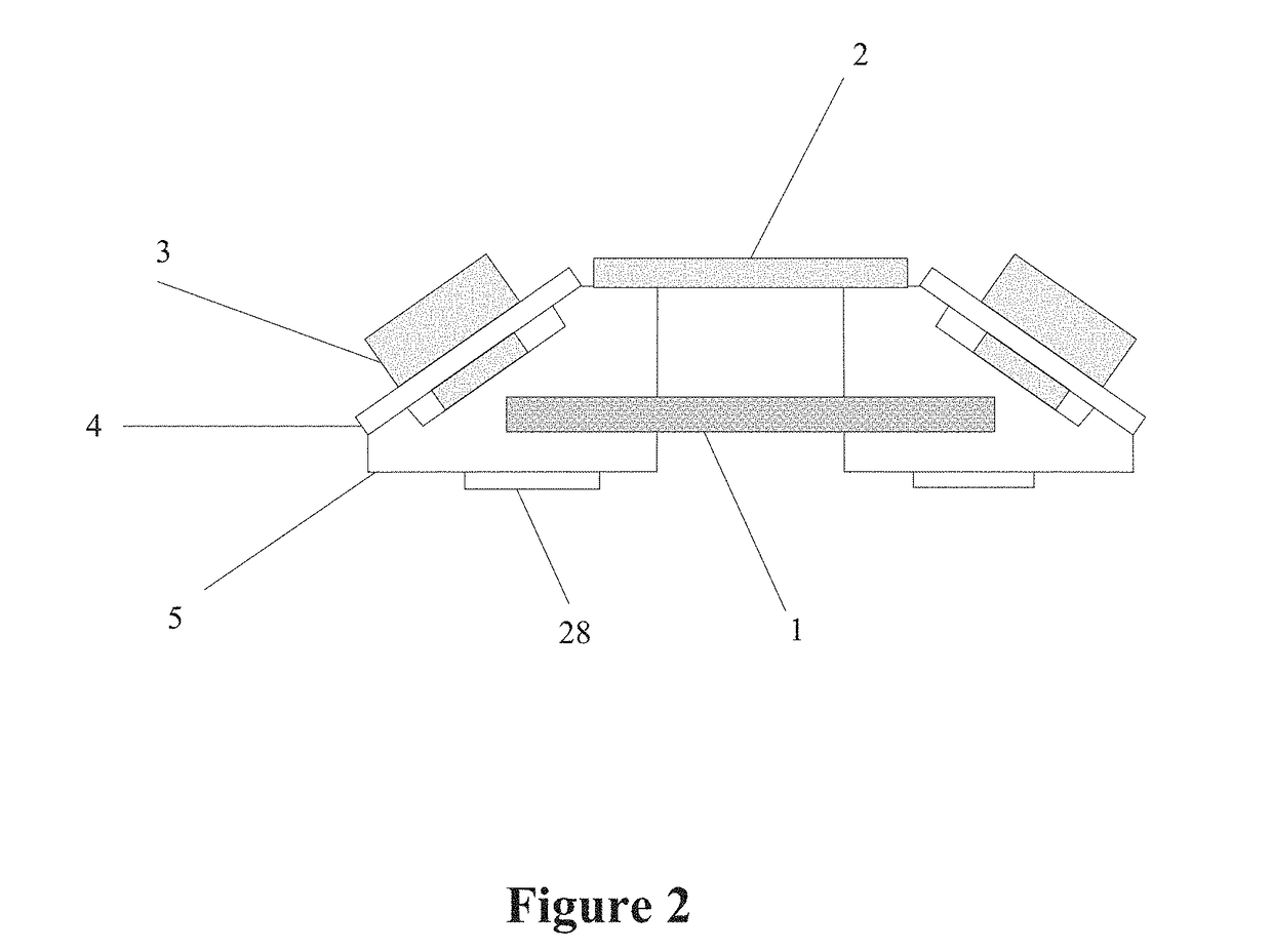
[0044]In the present embodiment, as shown in FIG. 3, the sensor device comprises plexiglass wedges 5, a magnetic base 7 and fixed plates 4. Threads are processed in the inclined planes of the plexiglass wedges 5, so that the ultrasonic transducers 3 are threadedly fixed with the plexiglass wedges 5. Cylindrical cavities 9 are processed inside the plexiglass wedge 5, with diameters slightly larger (such as 4 mm larger) than that of the circular chips of the transducers 3. ...

embodiment 3

[0056]Currently the measurement of residual stress by applying ultrasonic waves is mostly carried out for flat plates, while pipes can be seen everywhere in daily life. When the residual stress present in the inner or outer surface of the pipes is too large, a serious accident may be caused. Therefore, the stress detection of pipes has attracted more and more attention. When measuring the surface residual stress of curved surfaces such as pipes, an appropriate adjustment shall be made to the structure of the detected system.

[0057]When measuring the residual stress of the inner or outer surface of a pipe, the bottom of each plexiglass wedge 5 is machined, so as to have the same curvature as that of the pipe. Alternatively, a bottom surface contacting member with the same curvature of the pipe is mounted on the bottom surface of each plexiglass wedge 5. In addition, the magnetic base 7 can be mounted between two plexiglass wedges 5, providing a greater magnetic force to allow the coup...


PUM

PropertyMeasurementUnit
frequencyaaaaaaaaaa
diametersaaaaaaaaaa
thicknessaaaaaaaaaa

Abstract

A sensor device, comprising two symmetrically disposed sonolucent wedges (5), and a connecting piece for fixedly connecting the two sonolucent wedges (5); the upper surfaces of the sonolucent wedges (5) are provided with inclined planes; installation holes are formed on the inclined planes; transducers (3) are installed in respective installation holes; one transducer (3) is used to generate ultrasonic waves, and the other transducer (3) is used to receive the ultrasonic waves generated by the previous transducer (3). The residual stress detection system comprises a sensor device, an ultrasonic transmission card, and a data acquisition card.

Description

CROSS-REFERENCE TO RELATED APPLICATION(S)[0001]This application is the U.S. National Stage of International Patent Application No. PCT / CN2013 / 078687, filed on Jul. 2, 2013, which claims the priority of Chinese Patent Application No. 201210500278.6, filed on Nov. 29, 2012 with the Chinese Intellectual Property Office the disclosures of which are hereby incorporated in their entireties by reference.FIELD OF THE INVENTION[0002]The presented invention relates to a sensor device and residual stress detection system employing same. The residual stress at certain depth from the surface of metal materials can be detected by employment of ultrasonic longitudinal waves in the presented invention.BACKGROUND OF THE INVENTION[0003]The available techniques for the measurement of residual stress mainly include hole drilling and X-Ray diffraction. The measurement by hole drilling provides a higher accuracy, which is premised on damaged surface status of materials. The surface needs to be prepared b...

Claims


Application Information

Patent Timeline
Patent Type & Authority Patents(United States)
IPC IPC(8): G01N29/04G01N29/44G01N29/30G01N29/24G01N29/07G01N29/265G01L1/25
CPCG01L1/255G01N29/04G01N29/041G01N29/07G01N29/2487G01N29/265G01N29/44G01N29/4472G01N29/30G01N2291/102G01N2291/0289G01N2291/02827G01N2291/0421G01N2291/0425
Inventor XU, CHUNGUANGXU, LANGPAN, QINXUEXIAO, DINGGUOLI, XIAOGUO, JUNSONG, WENTAOLIU, HAIYANG
Owner BEIJING INSTITUTE OF TECHNOLOGYGY
Why Eureka
Try Eureka