
Phototherapy system and process including dynamic LED driver with programmable waveform

a phototherapy system and led driver technology, applied in light therapy, surgery, electroluminescent light sources, etc., can solve the problems of inability to maintain consistent led operation, grossly inadequate mechanical and electrical design of photobiomodulation and medically for phototherapy, and achieve the effect of expanding the flexibility of the program

Active Publication Date: 2018-01-23
APPLIED BIOPHOTONICS
View PDF16 Cites 15 Cited by
  • Summary
  • Abstract
  • Description
  • Claims
  • Application Information

AI Technical Summary

Problems solved by technology

In conclusion, prior attempts to adapt LED technology for photobiomodulation and medically for phototherapy suffer from grossly inadequate flaws in their mechanical and electrical design.
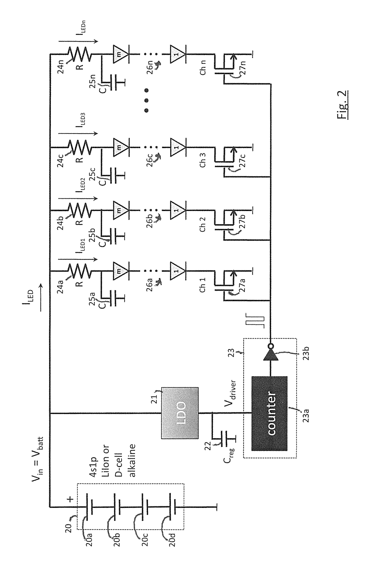
The LED driver circuitry used to implement early attempts at phototherapy essentially comprise constant voltage drive LED torchlights unable to maintain consistent LED operation under conditions of changing voltages, LED currents, or fault scenarios.
Operating essentially as fixed frequency lamp dimmer circuitry, they also lack the ability to facilitate pattern sequencing and waveform synthesis—sequences and waveforms potentially beneficial in maximizing photobiomodulation and the therapeutic benefit therewith.
Similarly inadequate, the hardware of present day LED arrays suffer from mediocre mechanical design resulting in poor reliability from excessive wire interconnections in the LED array and an inability to maintain a constant position or conform the shape of an LED array to a patient for a consistent optical penetration depth, especially during treatments necessarily exceeding tens of minutes, or longer.
Moreover, in their present form, such HDTV backlight drivers do not enable or even anticipate the need for generating complex waveforms, performing algorithmic sequencing, synthesizing varying frequencies, or driving inhomogeneous LEDs, ones of differing construction, wavelength and forward voltages.

Method used


Image

  • Phototherapy system and process including dynamic LED driver with programmable waveform
  • Phototherapy system and process including dynamic LED driver with programmable waveform
  • Phototherapy system and process including dynamic LED driver with programmable waveform

Examples


Embodiment Construction

Principles of Photobiomodulation

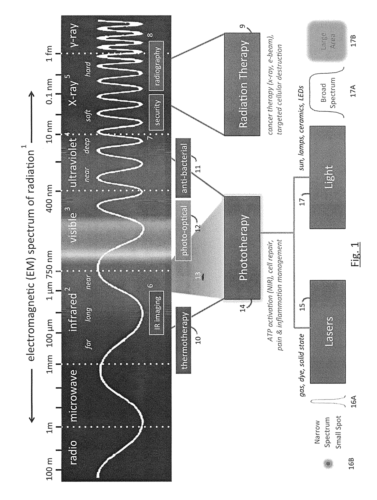
[0137]Photobiomodulation involves the controlled delivery of photons into living cells and tissue stimulating a biochemical response. When applied to medical science, the use of photobiomodulation to produce a beneficial or therapeutic result is herein referred to as “phototherapy”. A number of variables can affect photobiomodulation, including the organism, tissue, cell, or organelle being illuminated; the wavelength(s) of the light used, the absorption depth and scattering properties of the light at the impinging wavelength in the targeted and intervening tissue; the power, timing, duration, and frequency of the photoexcitation, including the potential sequencing of multiple wavelengths, the specific biochemical reaction being affected, and in therapeutic cases the nature of the injury or condition requiring treatment.

[0138]FIG. 8A schematically illustrates in cross section, the elements of a phototherapy delivery system, including a flexible circui...


PUM


Abstract

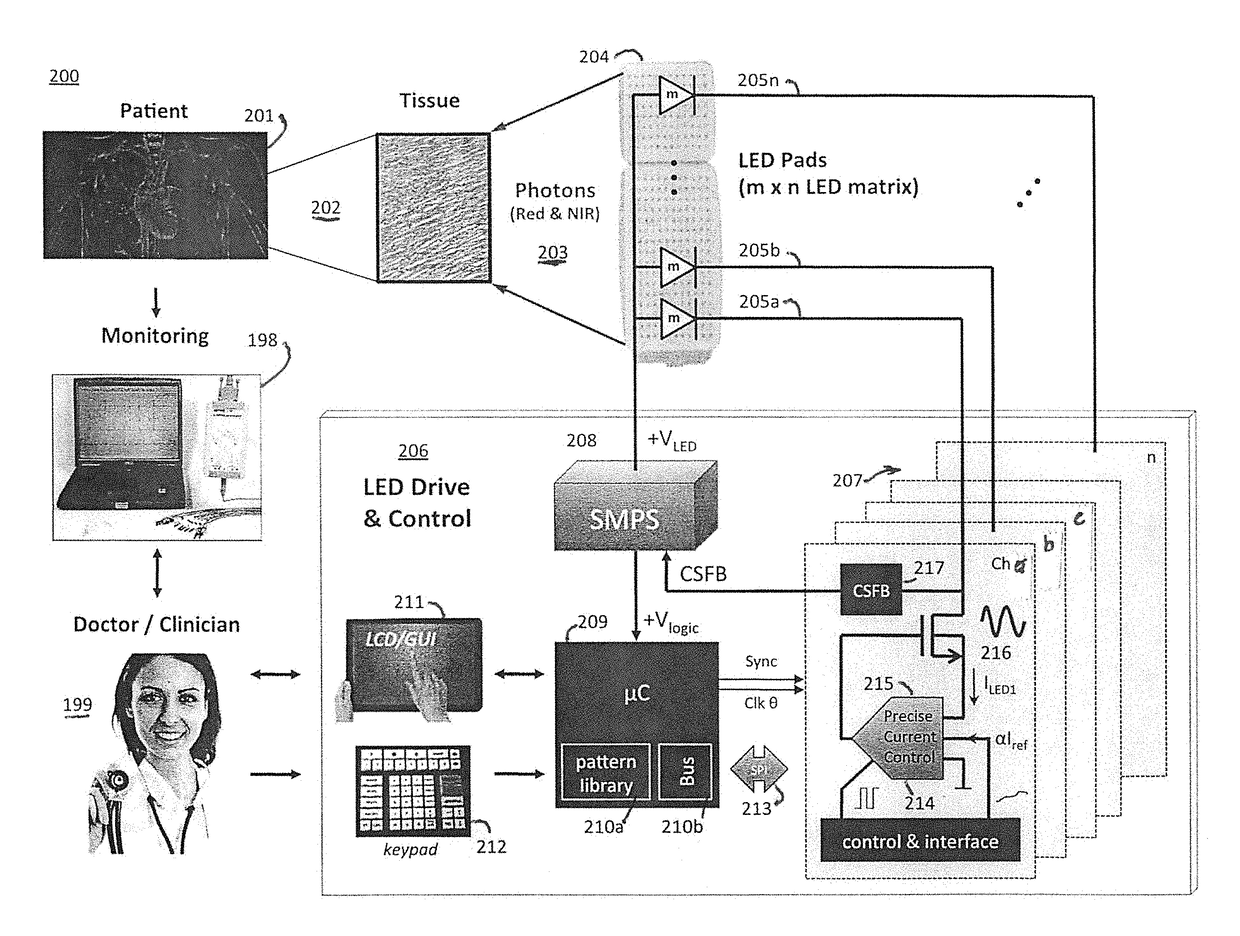
A phototherapy or photobiomodulation process employing the application of electromagnetic radiation (EMR) to a living organism, typically a human being. The EMR is generated by one or more strings of LEDs and is programmed to emit one or more wavelengths, typically in the visible and infrared portions of the spectrum, the EMR in each wavelength being delivered in pulses having specified on-times, off-times, photoexcitation frequencies, duty factors, phase delays, and power amplitudes. A system for providing such EMR includes a microcontroller having a pattern library of algorithms, each of which defines a particular sequence of synthesized pulses, and an application pad, preferably flexible, containing the LED strings.

Description

CROSS-REFERENCE TO RELATED APPLICATION[0001]This application claims the priority of Provisional Application No. 61 / 723,950, filed Nov. 8, 2012, which is incorporated herein by reference in its entirety.SCOPE OF INVENTION[0002]This invention relates to biotechnology for medical applications, including photobiomodulation and phototherapy.BACKGROUND OF INVENTIONIntroduction[0003]It is well known that electromagnetic radiation, a fundamental energy permeating the entire universe, affects living organisms in a wide variety of ways. Depending on the frequency or wavelength of the radiation and on its intensity or power level, electromagnetic radiation, also known as EMR, may be beneficial or hazardous to living creatures.[0004]Although radio waves and low power microwaves used in cell phones are largely considered benign, deep UV (ultraviolet light) and x-rays are known to be carcinogenetic and potentially life threatening to living creatures even at moderate doses. Still other frequencie...

Claims


Application Information

Patent Timeline
Patent Type & Authority Patents(United States)
IPC IPC(8): A61N5/06A61B18/18H05B33/08H05B44/00
CPCH05B33/08A61N5/06H05B33/0803H05B33/0866H05B33/0827A61N2005/0651A61N2005/0626H05B45/24H05B45/46H05B45/325H05B45/36H05B45/395H05B45/3725H05B45/56H05B44/00H05B45/00
Inventor WILLIAMS, RICHARD K.
Owner APPLIED BIOPHOTONICS
Learn More