Dental articulator

a technology of articulator and articulator, which is applied in the field of dental articulators, can solve the problems of difficult use, loose alignment, and high cost of plastic bases, and achieve the effects of convenient installation and removal, low cost, and simple construction

Active Publication Date: 2018-02-06
ELNAJJAR JEAN J
View PDF26 Cites 2 Cited by
  • Summary
  • Abstract
  • Description
  • Claims
  • Application Information

AI Technical Summary

Benefits of technology

[0025]Another significant feature and advantage of the present invention is that the magnetically coupled set screw and rotatable extension rod allow relative rotation between the set screw and the rotatable extension rod thereby allowing the ball of the model anchor to pivot in the cavity of the ball socket about the longitudinal axis of the transverse portion of the articulator member.
[0026]Another significant feature and advantage of the present invention is that the magnetically coupled set screw and rotatable extension rod allow the set screw and the rotatable extension rod to be easily installed and removed as a unit, and to be advanced and retracted longitudinally in the transverse portion of the articulator member when the set screw is rotated, thereby allowing the ball of the model anchor to be snap fitted into the ball cavity of the socket portion and to be properly positioned in the socket without interference.
[0027]A further feature and advantage of the present invention is that the magnetically coupled set screw and rotatable extension rod allow the set screw and the rotatable extension rod can be handled and manipulated as a single unit and eliminate the need for manually installing and positioning separate small shims and plungers that can be accidentally be dropped and lost.
[0028]A still further feature and advantage of the present dental articulator is that it is simple in construction, inexpensive to manufacture, and rigged and reliable in operation.
[0029]Other features and advantages of the invention will become apparent from time to time throughout the specification and claims as hereinafter related.

Problems solved by technology

Repeated use wears down the male stud, causing loose snapping with the female receiver, thus making the alignment loose.
This system requires plastic bases that are relatively expensive, as is the non-disposable dental articulator.
Both systems require articulators that are difficult to use and are expensive.
Some of the limitations of the Huffman devices are: 1) the difficulty in positioning the upper and lower casts while gluing their socket joints; 2) inability to make adjustments after gluing the socket joints; 3) inability to make adjustments / corrections to the lateral and vertical placement of the ridge tabs after gluing; 4) difficulty in storing dental casts due to space taken by the non-removable articulator; and 5) expense associated with not being able to reuse articulators on different casts.
Some of the problems with the ball mounting arrangement of the Callne Patent, U.S. Pat. No. 7,112,061, are that it requires several small parts that can become lost or misplaced, it is difficult to assemble the rear socket and the model connector onto the ball, and the amount of rotational movement is limited by the difference in diameters between the outside diameter of the bolt and the inside diameter of the bore through the ball.
One of the problems associated with dental articulators having articulator arms that are attached to the dental cast by adjustable ball and socket joints in which the ball is secured in place with a set screw threadedly mounted onto the socket is that the set screws are very small and are prone to being accidentally dropped and easily lost.
Another problem with small set screw members is that their tip end has a very small surface area relative to the surface of the ball, thus, it is difficult to apply sufficient force to effectively frictionally engage the ball against the inner wall of the socket to prevent slippage, and they are prone to cause galling of the ball surface.
One of the problems associated with dental articulators which provide a shim or plunger between the set screw and the ball is that the shim or plunger is small and difficult to install and remove and can be accidentally dropped and easily lost.
Another problem with the dental articulators which provide a shim or plunger between the set screw and the ball is that the shim or plunger is typically unsupported and can drop into the socket cavity making it difficult to install and properly position the ball in the socket.

Method used


Image

  • Dental articulator
  • Dental articulator
  • Dental articulator

Examples


Embodiment Construction

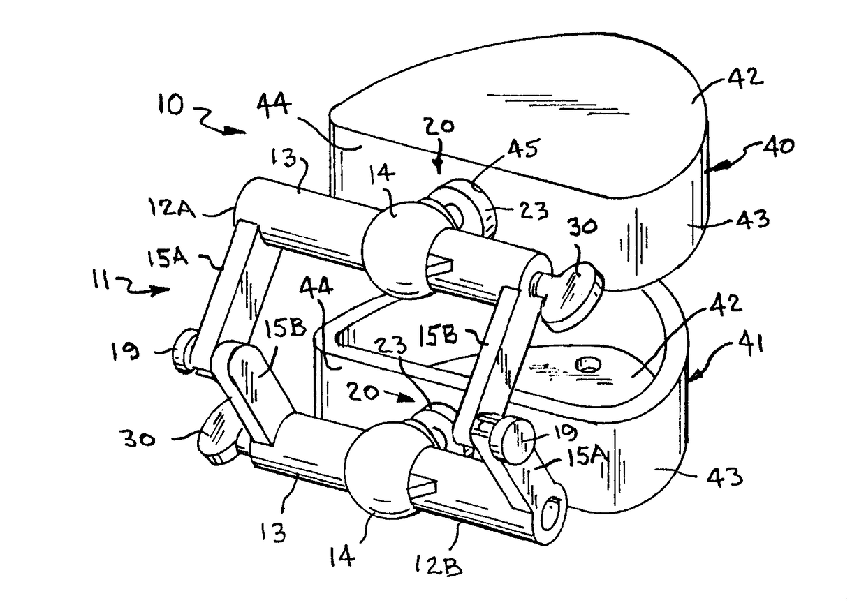
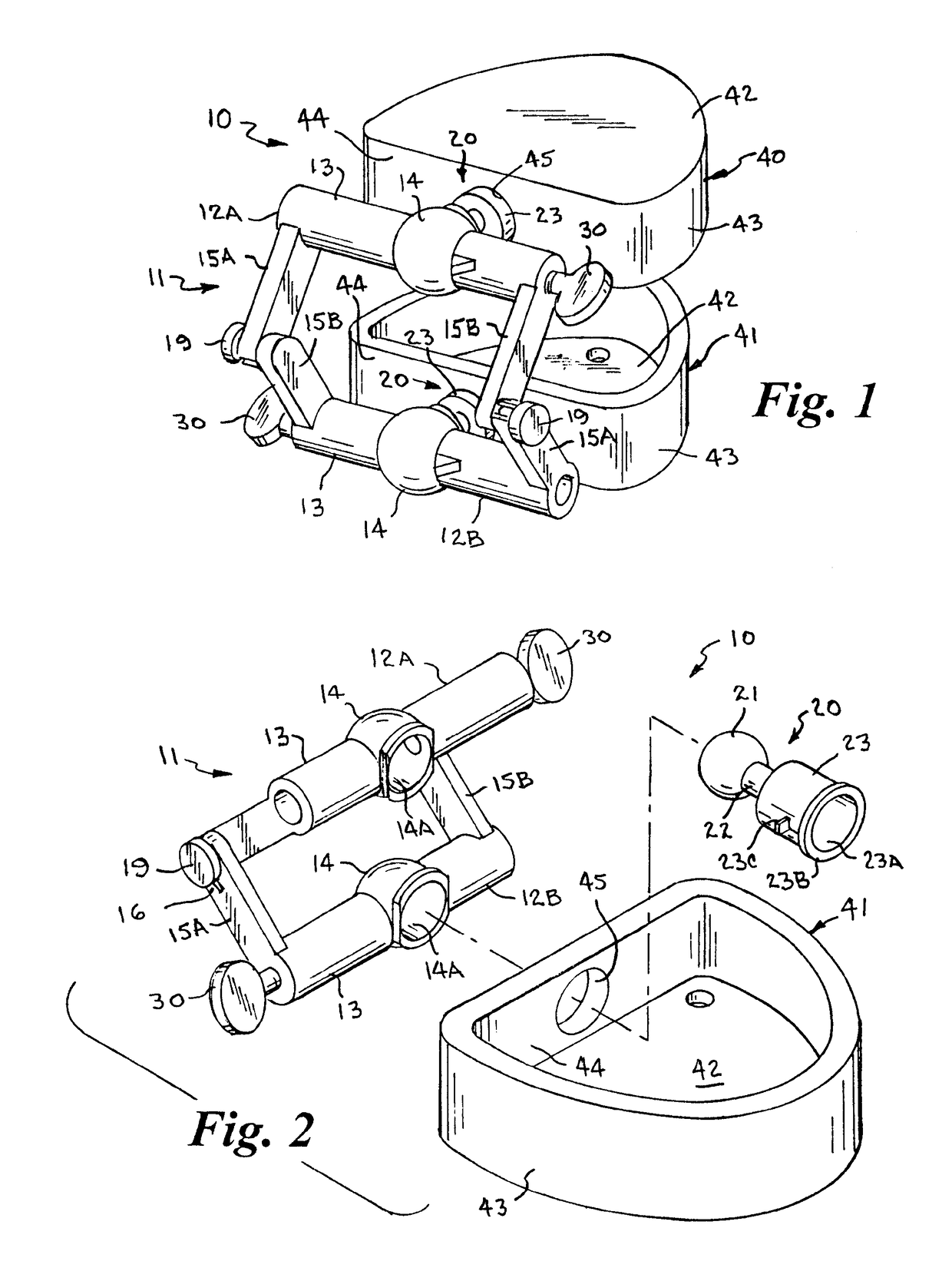
[0041]Referring to the drawings by numerals of reference, there is shown in FIGS. 1 and 2, an example of a preferred embodiment of a dental articulator apparatus 10, in accordance with the present invention. The dental articulator apparatus 10 includes an articulator 11 having an upper and a lower, generally U-shaped, articulator arm 12A and 12B, respectively, each integrally molded and having a generally cylindrical transverse portion 13 with a generally spherical ball socket 14 intermediate its opposed ends and flat laterally spaced link members 15A and 15B at each end of the transverse portion, the outer ends of which are pivotally connected together. The integrally molded link members 15A, 15B, extend from the ends of the transverse portion 13 along parallel spaced planes perpendicular to a longitudinal axis extending through the transverse portion. A model anchor 20 having a ball 21 at one end is rotatably received in the ball socket 14 of the transverse portion 13 of each arti...


PUM


Abstract

A dental articulator apparatus and method of forming dental casts utilizing a dental articulator having pivotally connected upper and lower arms that each have a ball socket which receives a ball at the outer end of a respective model anchor, the opposed end of which is cast into a dental model. The model anchor ball is adjustably secured in the ball socket of the articulator arms by a set screw coupled with a rotatable magnetic extension rod that are installed, removed, advanced, and retracted as a unit and allow relative rotation between the set screw and the extension rod to facilitate fitting and positioning the ball in the socket when the set screw is loosened, and eliminate manually installing and positioning separate small shims and plungers that can be accidentally dropped and lost.

Description

BACKGROUND OF THE INVENTION[0001]1. Field of the Invention[0002]The present invention relates generally to a device and method for a dental articulator for use with dental model casts, and, more specifically, to a dental articulator that is easily adjustable by the dental laboratory technician and / or dentist to align, as desired, the upper and lower dental model casts.[0003]2. Background Art[0004]Dental articulators, which hold and align together positive dental impressions, are well known in the prior art. Articulators are used to align the upper (maxilla) dental model with the lower (mandible) dental model, to simulate current or desired occlusion. By recreating the teeth and their occlusion (alignment) in model form, false teeth, caps and other dental prosthetics can be made in the precise size and shape necessary for the patient's mouth.[0005]To create the dental models (casts), the dentist makes a negative impression of the patient's teeth. This impression may be a full mold (b...

Claims


Application Information

Patent Timeline
Patent Type & Authority Patents(United States)
IPC IPC(8): A61C11/00A61C11/08
CPCA61C11/08
Inventor ELNAJJAR, JEAN J.
Owner ELNAJJAR JEAN J
Why Eureka
Try Eureka