System for changing the pitch of the blades of a propeller

a technology of blades and propellers, which is applied in the direction of rotors, machines/engines, liquid fuel engines, etc., can solve the problems of too many leakage risks, and achieve the effect of preventing high magnitude aerodynamic forces

Active Publication Date: 2018-02-06
SN DETUDE & DE CONSTR DE MOTEURS DAVIATION S N E C M A
View PDF17 Cites 3 Cited by
  • Summary
  • Abstract
  • Description
  • Claims
  • Application Information

AI Technical Summary

Benefits of technology

[0011]Thus, by virtue of the invention, the number of radial arms used for controlling, via the rotary common ring and the connecting mechanisms, all of the propeller blades can be reduced as, therefore, can the ensuing problems of sealing the turbomachine casings through which the arms pass. Specifically, there is no longer any need to have the same number of arms as there are blades because the ring is able to distribute and transmit the force of the actuator to the pivot pins of the blades. As the regions in which arms pass through the casings are reduced, so too are the risks of leaks.
[0013]Advantageously, the translationally movable rotary ring has a diameter substantially the same as at the diameter of a support ring that supports the pivot pins of the blades, so as to lie at substantially the same radial position as these. The control of the blades is thus relocated to the engine nacelle, at a radius distant from the actuator and on the outside of the casings through which the arms pass, so that there is no longer any need to have one radial arm per blade to be controlled because it is the common ring, thus radially offset, which takes care of blade orientation.
[0018]Moreover, each intermediate connecting mechanism of the transmission device may comprise two link rods which are articulated to one another, one of them also being articulated to a fastening support for securing the ring and the other also being articulated to the pivot pin of the corresponding blade of the propeller, the two link rods of each mechanism being substantially aligned parallel to the axis of rotation of the ring and perpendicular to the axis of pivoting of the blade. These link rods of the connecting mechanisms allow the translational movement of the rotary ring to be converted into a rotation of the blades in the manner of a connecting-rod / crank system.
[0020]Indeed it is known that the counterweights are used so that the centrifugal force generated spontaneously returns the blades to the feathered position if there is a malfunctioning of the orientation system as a result, for example, of a defective hydraulic feed to the actuator. These counterweights are therefore used as levers to control the angular setting of the blades by applying a force that is exerted in the direction of the axis of the turbomachine, unlike the solutions of the prior art in which the force delivered by the actuator is transmitted directly, via a radial arm or shaft, along the axis of the blade making it necessary to have one radial shaft per blade. Further, advantageously, to prevent high magnitude aerodynamic forces exerted on the blades from being transmitted by the counterweights to the device (ring and connecting mechanisms), the stiffening means is designed to absorb these forces without transmitting them to the device which is then able to enjoy problem free operation.

Problems solved by technology

As the regions in which arms pass through the casings are reduced, so too are the risks of leaks.

Method used


Image

  • System for changing the pitch of the blades of a propeller
  • System for changing the pitch of the blades of a propeller
  • System for changing the pitch of the blades of a propeller

Examples


Embodiment Construction

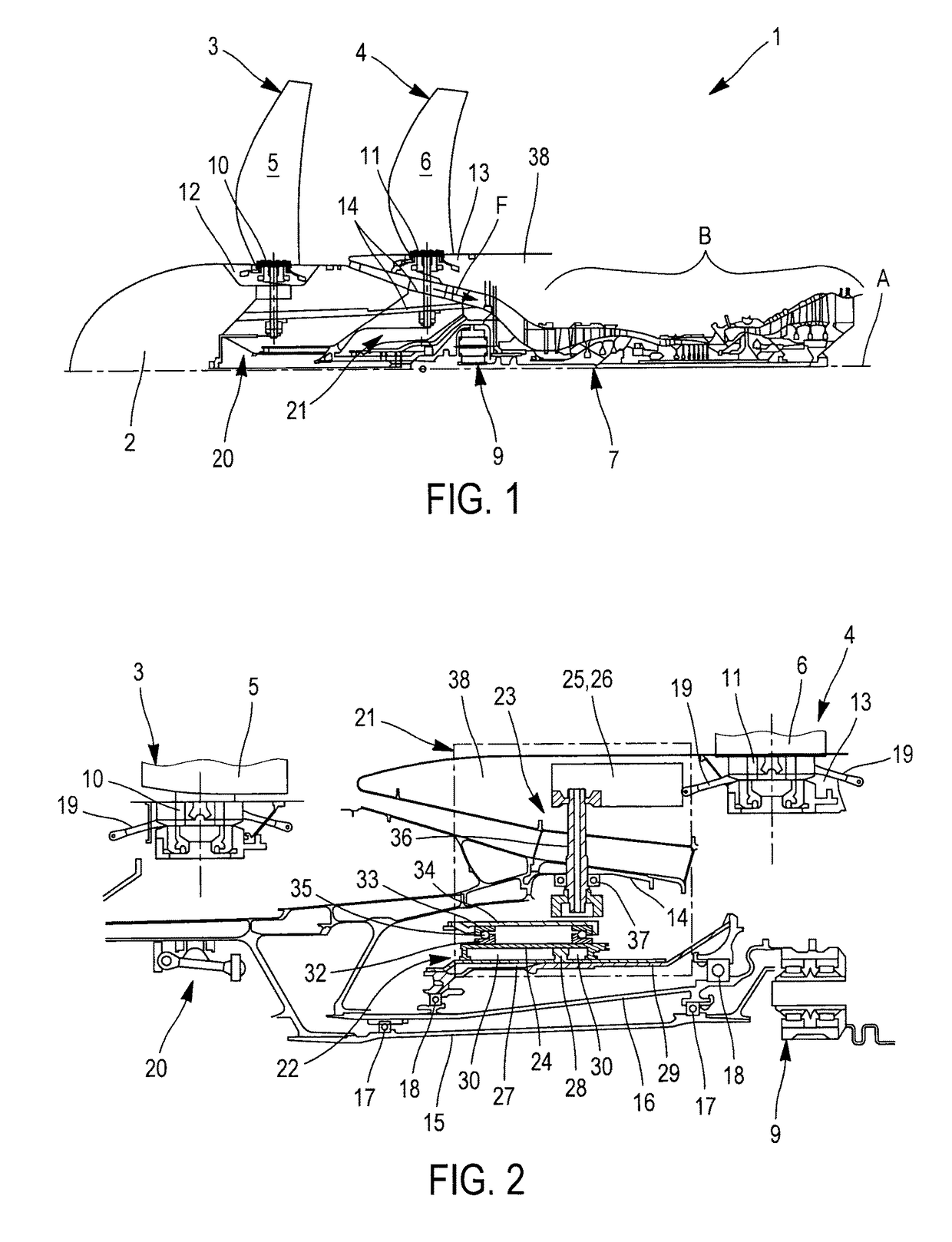
[0032]The turbomachine 1 depicted in FIG. 1 is a turbomachine with an upstream unducted fan, referred to more commonly in English as an “open rotor puller”, of longitudinal axis A.

[0033]Provided at the front 2 of the turbomachine 1 are two propellers 3, 4 that are coaxial about the axis A and counter rotating, forming the fan and the blades 5, 6 of which can be set at variable pitch angles to suit the various phases of flight, including taxiing along the ground, described hereinabove and encountered by the airplane equipped with these turbomachines.

[0034]As already indicated, the entire pulling front part 2 of the turbomachine is therefore able to rotate about the axis A and in order to do so is driven by the gas generating part 7, which is therefore downstream, where the compressors, combustion chamber and turbines indicated under the reference 8 can usually be found. The stream of air entering the part 7 is symbolized by the arrow F.

[0035]As shown by FIG. 1 and notably by FIG. 2, ...


PUM


Abstract

A system includes a linear-displacement fluidic actuator coaxial with the propeller, and a transmission device connecting the actuator to the blades that are to be controlled. The transmission device includes at least two radial arms arranged symmetrically with respect to the actuator and connected, on the inside, to a translationally mobile part of the actuator and, on the outside, to a translationally movable rotary transmission ring which is connected to the pivot pins of the blades by intermediate connecting mechanisms that convert the translational movement of the rotary ring brought about by the actuator into a rotation of the blades of the propeller.

Description

BACKGROUND OF THE INVENTION AND DESCRIPTION OF THE PRIOR ART[0001]The present invention relates to a system for changing or setting the pitch of the blades of a turbomachine propeller or rotor.[0002]More particularly, although not exclusively, the system is intended to be fitted to turbomachines made up of a pair of coaxial and counter rotating propellers, known in English as “open rotors” or “unducted fans”, the pair of propellers being likened to the fan of turbojet engines.[0003]There are two structural solutions that are currently being developed, one with the pair of propellers arranged downstream of the turbomachine, the open rotor being qualified as a “pusher”, and the other with the pair of propellers arranged upstream of the turbomachine, the open rotor being qualified as a “puller”.[0004]Without going into the advantages and disadvantages of these two solutions, which do not form part of the subject matter of the invention here, the pitch of the propeller blades is made ad...

Claims


Application Information

Patent Timeline
Patent Type & Authority Patents(United States)
IPC IPC(8): B64C11/38B64C11/30F01D7/00F02K3/072F04D29/36
CPCB64C11/38B64C11/306F01D7/00F02K3/072F04D29/362Y02T50/673F05D2220/36F05D2260/50F05D2270/64F04D29/323Y02T50/60
Inventor CURLIER, AUGUSTINBELMONTE, OLIVIER
Owner SN DETUDE & DE CONSTR DE MOTEURS DAVIATION S N E C M A
Why Eureka
Try Eureka