Chromatography columns

a chromatography column and column technology, applied in the field of liquid chromatography, can solve the problems of increasing the cost and complexity of instruments, slow separation and broader retention time peaks, and low sample capacity of non-porous particles, so as to maintain the loadability of the column, reduce the pressure of the flow, and maintain the effect of chromatographic efficiency and resolution

Active Publication Date: 2018-02-20
THERMO ELECTRON MFG
View PDF10 Cites 1 Cited by
  • Summary
  • Abstract
  • Description
  • Claims
  • Application Information

AI Technical Summary

Benefits of technology

[0014]The bed sections (and thus compartments, or sub-columns, containing the bed sections) are positioned in series along the length of the column, i.e. so that mobile phase flows through a first bed section, then through a second bed section and then optionally through any further bed section or sections. The bed sections are self contained so that particles of one bed section cannot mix with particles of an adjacent bed section, thereby separating the bed sections. A physical restriction (partition) is used to keep adjacent bed sections separate and improve the stability of the column bed. The use of a liquid-porous partition or barrier as a physical restriction between adjacent bed sections is a means for ensuring the self containment of the bed sections (i.e. a partition that allows passage of liquid but not the packed particles). A frit (i.e. a porous frit) is a suitable partition for this purpose, such as a steel frit. Other partitions could be a porous mesh, or a porous monolith, or a porous filter.
[0023]Of beneficial use are fused core particles wherein the thickness of the outer porous layer is similar or substantially the same for all the particles. Thus, in such embodiments, whilst the particle diameter of the fused core particles varies with distance along the column, the thickness of the porous outer layer of the particles preferably does not substantially vary with distance along the column. Instead, in such embodiments, it is the diameter of the non-porous core of the fused core particles that varies with distance along the column to thereby vary the total diameter. Thus, in the embodiments with a bed comprising a plurality of bed sections, all the particles in all the bed sections have similar or substantially the same thickness of their outer porous layer. A substantially constant thickness of the outer porous layer of the particles along the column length maintains a uniform mass transfer distance for all of the packed particles. This maintains chromatographic efficiency and resolution in the column. However, some embodiments are possible in which along the column length from inlet to outlet the thickness of the outer porous layer may reduce, i.e. as the sample progresses through the column.
[0024]Preferably, the particle diameter of the packed particles varies with distance along the column such that smaller particles are packed at the inlet end of the column and larger particles are packed at the outlet end. Using smaller diameter particles at the inlet end means that there is maximum surface area per unit volume at the part of the column where the sample is loaded, which maintains the loadability of the column. Employing larger diameter particles at the outlet end means that the pressure of the flow can be reduced compared to a column with only small particles throughout the whole column.
[0025]The invention provides the advantage that high column efficiency can be provided with lower pressure drop per unit length of the column. This reduction in operating pressure has benefits in terms of reduced cost of the instrumentation. Moreover, longer columns may be used to give higher chromatography efficiency without excessive pressure needing to be applied to the flow. The loadability of the column is maintained by providing the smallest particles at the inlet end of the column. Larger particles, preferably at the outlet end, are used to reduce the pressure drop.
[0026]The bed of the column, or any one or more bed sections thereof, may comprise an amount of non-porous particles additionally to the fused core particles, which may reduce the dispersion of a sample as it passes through the column and improve peak sharpness. The amount of such non-porous particles is a minor amount relative to the amount of fused core particles typically.

Problems solved by technology

Non-porous particles have a low sample capacity.
Larger porous particles tend to have longer mass transfer distances for the sample, which leads to slower separation and broader retention time peaks than with smaller porous particles.
Higher pressures increase the cost and complexity of the instrumentation.

Method used


Image

  • Chromatography columns
  • Chromatography columns
  • Chromatography columns

Examples


Embodiment Construction

[0044]In order to enable further understanding of the invention, but without limiting the scope thereof, various exemplary embodiments of the invention are now described with reference to the accompanying drawings.

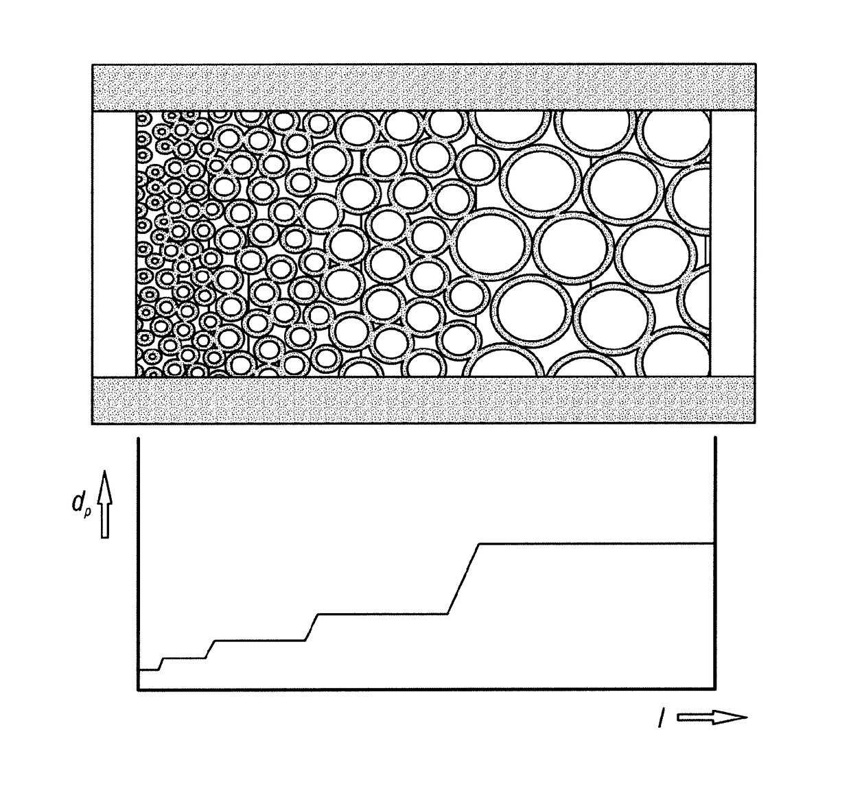
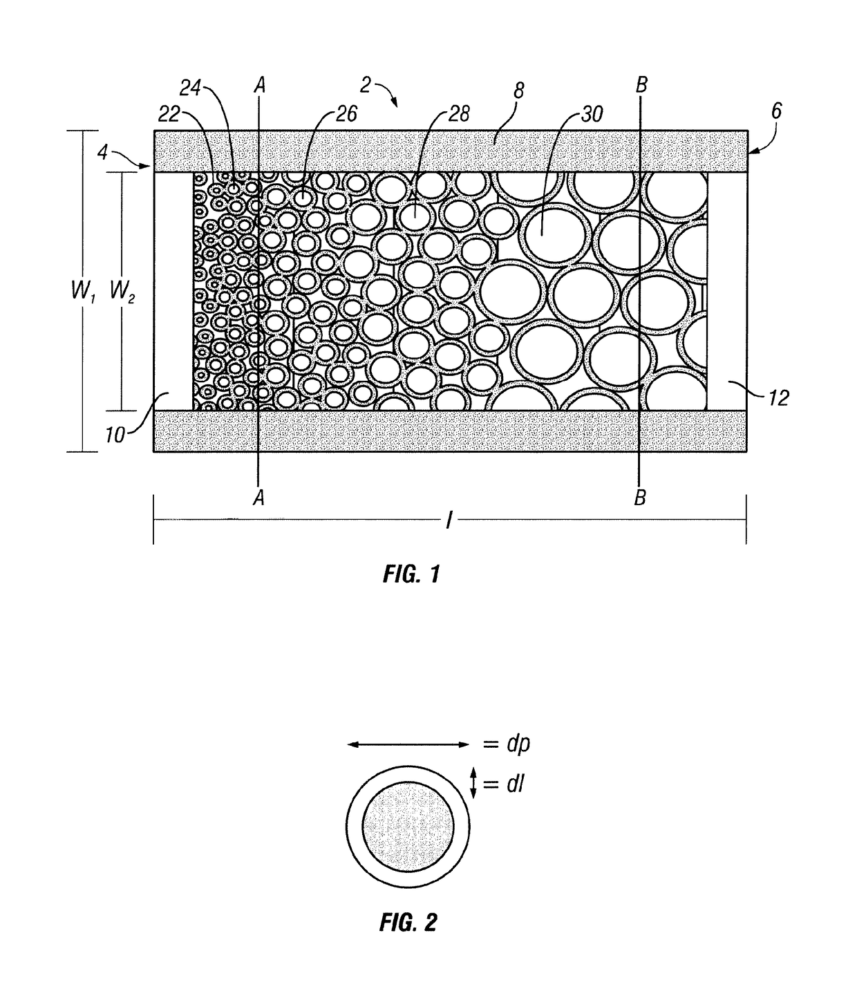
[0045]Referring to FIG. 1, there is shown a schematic arrangement of a chromatography column (2) packed with a bed of particles in accordance with the present invention. The Figure shows a cross-sectional side view of the column, i.e. a section taken longitudinally along the length of the column. The column comprises a tube (8), commonly made of metal such as stainless steel for example. The column has a circular cross section in transverse cross section, orthogonal to the length e.g. in a section through line A-A or B-B. The column has a length, l, an outer tube diameter, w1, and an inner tube diameter, w2, as shown. The column may be an HPLC column made of steel and of circular section. However, it will be appreciated that column shapes, geometries and materials other th...


PUM

PropertyMeasurementUnit
thicknessaaaaaaaaaa
diameteraaaaaaaaaa
diameteraaaaaaaaaa

Abstract

A chromatography column (2) containing a bed of packed particles (22, 24, 26, 28, 30), wherein the packed particles comprise fused core particles and the particle diameters of the packed particles vary along the column. Preferably, the particles (2, 24, 26, 28, 30) are arranged according to their average particle diameter, in order of increasing average particle diameter from the inlet end (4) to the outlet end (6). The bed may comprise a plurality of bed sections and each bed section has an average particle diameter calculated from the particles in that section and there are at least two different average particle diameter bed sections, wherein the particles of each bed are separated from particles of an adjacent bed by a partition that is liquid permeable to allow through a flow of mobile phase. A high column efficiency can be provided with lower pressure drop per unit length of the column.

Description

CROSS REFERENCE TO RELATED APPLICATIONS[0001]This application is a United States National Stage Application, under 35 U.S.C. §371, of International Application PCT / EP2013 / 069459, filed Sep. 19, 2013, entitled “IMPROVEMENTS IN AND RELATING TO CHROMATOGRAPHY COLUMNS,” which claims the priority benefit to Great Britain Patent Application No. 1216984.3, filed Sep. 24, 2012, entitled “Improvements in and relating to chromatography columns” and to Great Britain Patent Application No. 1216985.0, filed Sep. 24, 2012, entitled “Improvements in and relating to chromatography columns,” which applications are hereby incorporated herein by reference in their entireties.FIELD OF THE INVENTION[0002]This invention relates to the field of liquid chromatography.BACKGROUND OF THE INVENTION[0003]Liquid chromatography (LC) columns have been extensively developed and are used routinely in both analytical and preparative chromatography. The separation in a liquid chromatography column of a sample comprisi...

Claims


Application Information

Patent Timeline
Patent Type & Authority Patents(United States)
IPC IPC(8): G01N30/60B01D15/20G01N30/52B01J20/28B01J20/283B01J20/10
CPCG01N30/60B01D15/20B01J20/103B01J20/283B01J20/28004B01J20/28057G01N30/52G01N30/6069B01J20/28052G01N2030/524B01J2220/58G01N30/6039
Inventor RITCHIE, HARALD
Owner THERMO ELECTRON MFG
Why Eureka
Try Eureka