Intensity-based depth sensing system and method

a depth sensing system and intensity-based technology, applied in the field of depth sensing systems and methods, can solve the problems of limited depth sensing system dynamic range and inability to produce reflection at distant points in the scene, and achieve the effect of increasing the dynamic range of depth values

Active Publication Date: 2018-02-20
MITSUBISHI ELECTRIC RES LAB INC
View PDF8 Cites 5 Cited by
  • Summary
  • Abstract
  • Description
  • Claims
  • Application Information

AI Technical Summary

Benefits of technology

[0008]It is an object of some embodiments of the invention to increase a dynamic range of depth values that an intensity-based depth sensing system can determine. It is another object of some embodiments to provide an intensity-based depth sensing system suitable for depth sensing of outdoor scenes.
[0011]Some embodiments of the invention are based on a realization that dynamic range of the intensity-based depth sensing systems depends on a difference between the amount of light received from near and far points of the scene. Specifically, the reduction of such a difference can increase the dynamic range of the depth sensing system. Therefore, some embodiments of the invention vary the intensity profile of the transmitted light pulse to increase a uniformity of the light received from points at different depth.
[0012]In some embodiments, the integrated light reflected from the near points includes only a small portion of the transmitted light pulse, but of a high intensity due to low light dissipation. Conversely, the integrated light reflected from the distant points includes a greater portion of the transmitted light pulse, but of lower intensity due to high light dissipation. However, because of the pulse dissipation, the integration of the small portion of the light pulse but of high intensity can be significantly larger than the integration of the greater portion of the light but of lower intensity. Therefore, to reduce the difference between the integration of light reflected from near and distant points, some embodiments reduce the intensity of the portions of light pulse received from both the near and distant points, as compared with intensities of the light received only from the distant objects.
[0013]For example, some portions of the light pulse are received by the sensor as reflected from both the close and the distant points in the scene. However, some other portions of the reflected light pulse are received only from the more distant points due to specifics of light propagation and gated integration of the intensity-based depth sensing systems. Therefore, some embodiments vary, e.g., reduce, the intensity of commonly received portions of the light pulse with respect to the intensities of the portions of the light pulse received only for the distant points. In such a manner, the lower intensity of the light reflected from near points can help to avoid saturation, while the lower intensity of the light reflected from the distant points is compensated by additional portions of light pulse with higher intensity that is received only from the distant points.
[0014]For example, for the light pulses with constant, i.e., flat, intensity profile, as the distance increases, the area of the pulse being integrated increases at a fixed rate that is proportional to the distance. However, for the light pulses with decreasing intensity profile, as the distance increases, the area of the pulse being integrated increases at an increasing rate, e.g., quadratic or cubic to the distance. On the other hand, the light pulse is dissipated as distance increases by a rate higher than the increase in the distance. Therefore, by using a decreasing intensity profile, more distant points produce stronger measurements compared to those produced when using pulses with flat intensity profiles. Therefore, the overall gain of the system can be reduced, so that near points do not saturate the sensors, while more distant points are still detectable by the sensors.

Problems solved by technology

The dynamic range of the intensity-based depth sensing system is limited by the capacity and sensitivity of the sensors of the depth sensing system.
On the other hand, if the intensity is too low, then the distant points in the scene can fail to receive sufficient light to produce a reflection that can be detected by the sensors.

Method used


Image

  • Intensity-based depth sensing system and method
  • Intensity-based depth sensing system and method
  • Intensity-based depth sensing system and method

Examples


Embodiment Construction

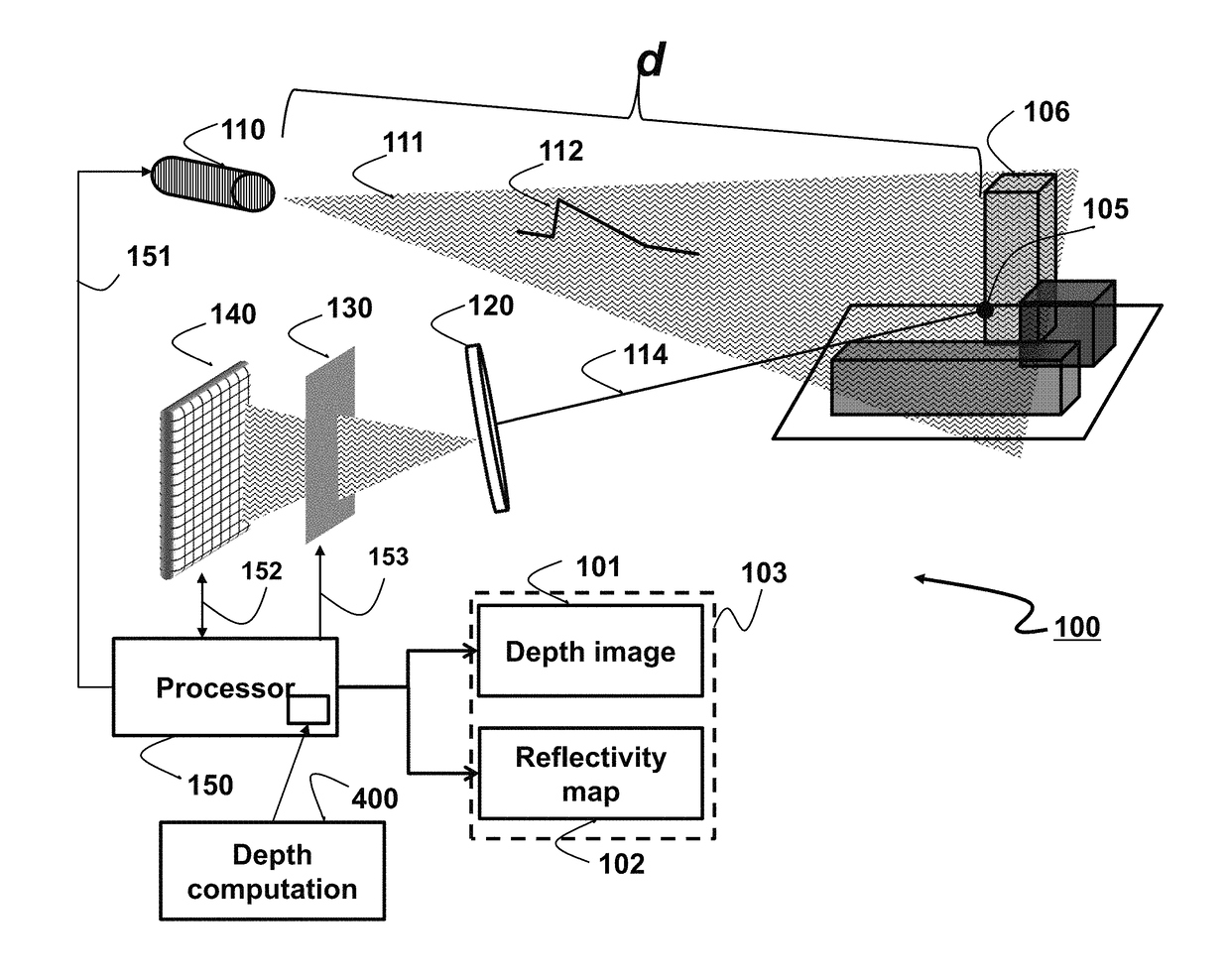
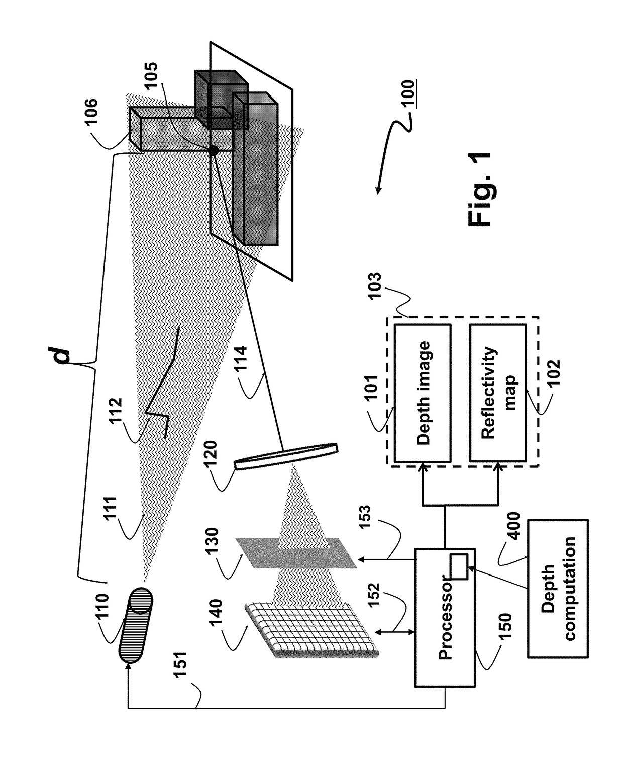
[0022]FIG. 1 shows a schematic (not a block) diagram of a system 100 for determining a depth image 101 indicating distances to points in a scene 106 according to some embodiments of an invention. The system includes a light source 110 for generating and directing a set of light pulses toward the scene. For example, the light source 110 can transmit a wide-beam light pulse 111 with a certain intensity profile 112, i.e., a shape of the pulse. In various embodiments, the intensity profiles of the light pulses are shaped according to desired properties for the sensing system. In one embodiment, the light source is a laser. However, other embodiments use different light sources, such as a photodiode, suitable for transmitting light source with different intensity profiles.

[0023]The light pulse propagates to the scene 106, illuminates the scene and is reflected by the points in the scene. Each point 105 of the scene reflects 114 the incident light back to the system. The reflected light p...


PUM


Abstract

A system for determining a depth image representing distances to points of a scene includes a light source for generating and directing a set of light pulses toward the scene and a set of sensors for detecting and integrating light reflected from the scene. Each sensor is associated with a point in the scene and generates a signal indicative of an amount of light reflected from the point in the scene and reaching the sensor during a period of time. The system includes at least one processor for coordinating operations of the light source and the set of sensors and for determining the depth image having intensity values representing the distances to the points in the scene. The processor commands the light source to generate the set of light pulses including a first pulse with a first intensity profile having portions of identical lengths with different integrated intensities.

Description

FIELD OF THE INVENTION[0001]This invention relates to depth sensing systems and methods, and more specifically to determining a depth image indicating distances to points of objects in a scene.BACKGROUND OF THE INVENTION[0002]Depth sensing is a technology for measuring depths in a scene, i.e., the distances from a sensor to points of in the scene. Types of depth sensing include measurements using structured light cameras, stereo cameras, and depth sensing cameras based on time-of-flight (TOF) measurements of the light reflected from the scene.[0003]For example, structured light cameras illuminate the scene using spatially modulated light. Because of the physics of the light propagation, the structured light cameras have fixed angular resolution, resulting in decrease of the depth resolution as the depth of the scene increases.[0004]A stereo camera records the same scene from two different viewpoints. The depth of each point in the scene is determined using disparities between the po...

Claims


Application Information

Patent Timeline
Patent Type & Authority Patents(United States)
IPC IPC(8): G01S17/89G01S17/32G01S7/486G01S17/10G01S7/484G01S7/4861G01S17/18G01S17/894
CPCG01S17/89G01S7/484G01S17/32G01S17/107G01S7/4861G01S17/18G01S17/894
Inventor BOUFOUNOS, PETROS TKADAMBI, ACHUTA
Owner MITSUBISHI ELECTRIC RES LAB INC
Why Eureka
Try Eureka