
Anisotropic conductive film, anisotropic conductive film production method, connecting method, and bonded structure

a technology of anisotropic conductive film and anisotropic conductive film, which is applied in the direction of printed circuit aspects, transportation and packaging, and association of printed circuit non-printed electric components, etc., can solve the problems of insufficient insulation resistance between adjacent electrodes (terminals), low particle capture rate, and insufficient insulation resistance between adjacent electrodes in a substrate or electronic component. achieve the effect of enhancing conduction resistan

Active Publication Date: 2018-03-20
DEXERIALS CORP
View PDF27 Cites 0 Cited by
  • Summary
  • Abstract
  • Description
  • Claims
  • Application Information

AI Technical Summary

Benefits of technology

The present invention solves various problems in the art by providing an anisotropic conductive film that can achieve insulation resistance between adjacent terminals in anisotropic conductive connection of fine-pitch and excels in conduction resistance and particle capturing rate. This film can be produced using a specific method and can be utilized in a connecting method and bonded structure. Overall, this invention addresses the technical problem of improving the performance of anisotropic conductive films in high-density connections.

Problems solved by technology

When an electrode of an electronic component, which is downsized, integrated, and has a small pitch between electrode, is connected using the aforementioned anisotropic conductive film, there is a problem that insulation resistance between the adjacent electrodes (terminals) is not sufficient.
In accordance with this technique, however, there is a problem that a short circuit is caused as particles of the metal powder are in contact with each other at the time of anisotropic conductive connection, and insulation resistance between adjacent electrode in a substrate or electronic component cannot be sufficiently maintained.
Since a number of metal particles to be linked is not specified, moreover, there are particles in a chain, which do not effectively function for anisotropic conductive connection, and therefore a particle capturing rate tends to be low.
Therefore, a large number of the conductive particles are linked in the form of a chain due to the applied magnetic field, As a result, insulation resistance between adjacent electrodes in a substrate or electronic component cannot be sufficiently maintained, and therefore there is a problem that a short circuit is caused.
As a large number of the conductive particles are linked in the form of a chain, moreover, there are conductive particles in a chain, which do not effectively function for anisotropic conductive connection, and therefore a particle capturing rate tends to be low.

Method used


Image

  • Anisotropic conductive film, anisotropic conductive film production method, connecting method, and bonded structure
  • Anisotropic conductive film, anisotropic conductive film production method, connecting method, and bonded structure
  • Anisotropic conductive film, anisotropic conductive film production method, connecting method, and bonded structure

Examples


production example 1

[0132]To a solution, in which a blending ratio of divinyl benzene, styrene, and butyl methacrylate was adjusted, benzoyl peroxide was added as a polymerization initiator, and the resultant was homogeneously stirred at high speed with heating to proceed to a polymerization reaction, to thereby obtain a particle dispersion liquid. The particle dispersion liquid was filtered, followed by vacuum dried, to thereby obtain a block product that was an aggregated product of the particles. Then, the block product was pulverized, to thereby obtain crosslinked polystyrene particles having the average particle diameter of 3 μm.

example 1

—Production of Conductive Particles 1—

[0164]Resin particles, to each of which a metal plated layer was provided, were obtained in the same manner as in Comparative Example 2, provided that the concentration of P in the Ni—P (nickel-phosphorus) plating was changed to the concentration of P depicted in Table 1-1.

[0165]Subsequently, the resin particles, to each of which the metal plated layer had been provided, were covered with an insulating layer in accordance with the method described in the paragraphs [0013] to [0014] in JP-S No. 04-362104. Moreover, whether or not each of the resin particles each provided with the metal plated layer were covered with the insulating layer was confirmed by observing the particles under the metallurgical microscope

[0166]Anisotropic Conductive Film 3 and Bonded Structure 3 were obtained in the same manner as in Comparative Example 1, provided that the conductive particles were replaced with Conductive Particles 1.

[0167]Anisotropic Conductive Film 3 an...

examples 2 and 3

[0168]Anisotropic Conductive Films 4 to 5, and Bonded Structures 4 to 5 were obtained in the same manner as in Example 1, provided that, in the production of the conductive particles, the concentration of P in the Ni—P plating was changed to the concentration of P depicted in Table 1-1.

[0169]Note that, the average thickness of the plated layer was 100 nm in both Examples 2 and 3. Moreover, whether or not each of the resin particles each provided with the metal plated layer were covered with the insulating layer was confirmed by observing the particles under the metallurgical microscope Anisotropic Conductive Films 4 to 5 and Bonded Structures 4 to 5 as obtained were subjected to the evaluations in the same manner as in Comparative Example 1. The results are presented in Table 1-1.


PUM

PropertyMeasurementUnit
particle diameteraaaaaaaaaa

Abstract

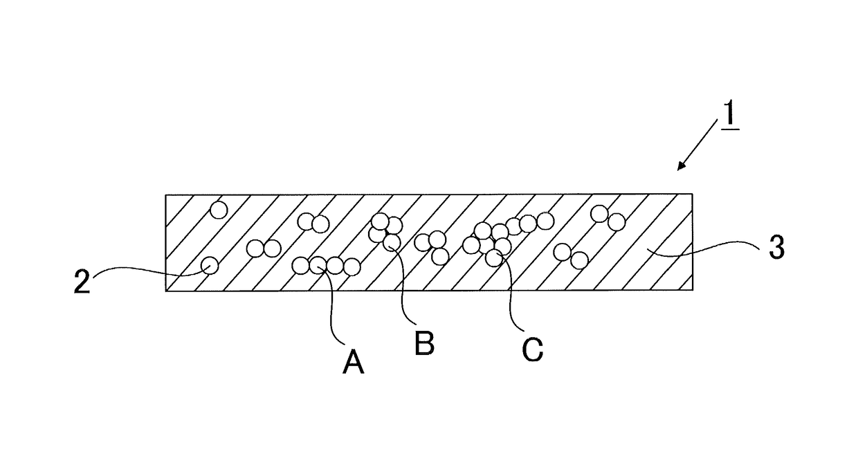
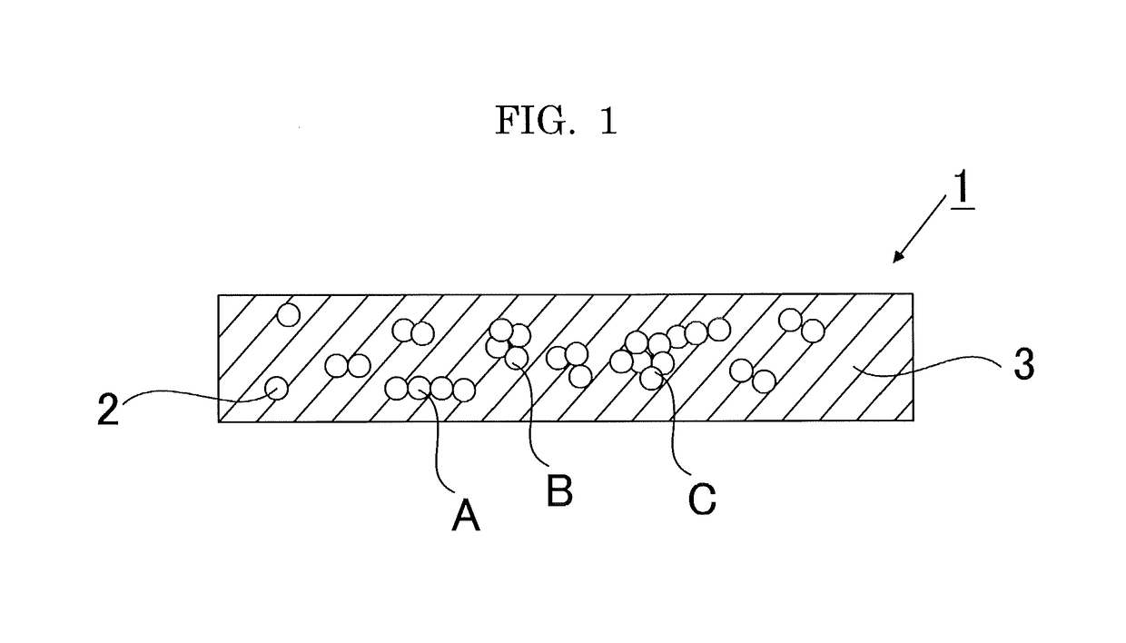
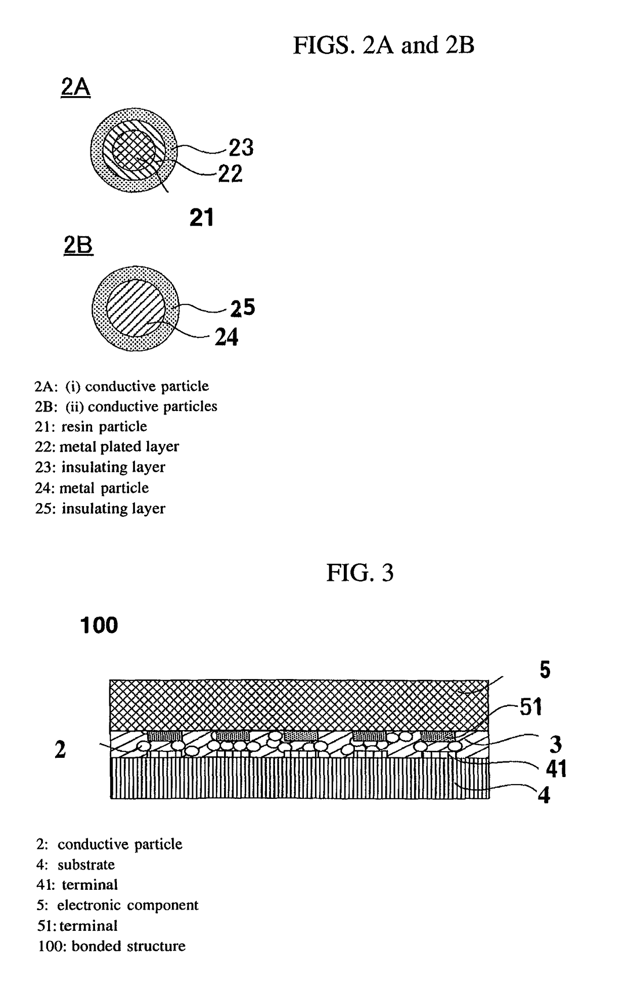
To provide an anisotropic conductive film, which contains conductive particles, wherein the anisotropic conductive film is an anisotropic conductive film configured to anisotropic conductively connect a terminal of a substrate with a terminal of an electronic component, wherein the conductive particles are conductive particles, in each of which a metal plated layer and an insulating layer are sequentially provided on a surface of a resin particle, or conductive particles, in each of which an insulating layer is provided on a metal particle, or both thereof, and wherein 3.0 to 10.0 conductive particles are linked together on average.

Description

CROSS-REFERENCE TO RELATED APPLICATION[0001]This application is a continuation application of International Application PCT / JP2012 / 070138 filed on Aug. 8, 2012 and designated the U.S., the entire contents of which are incorporated herein by reference.BACKGROUND OF THE INVENTION[0002]Field of the Invention[0003]The present invention relates to an anisotropic conductive film capable of electrically and mechanically connecting an electronic component, such as an IC chip, a liquid crystal display panel (LCD panel) of a liquid crystal display (LCD), and relates to a method for producing the anisotropic conductive film, a connection method and bonded structure using the anisotropic conductive film.[0004]Description of the Related Art[0005]Conventionally, a connecting material in the shape of a tape, obtained by coating a release film with a thermoset resin containing conductive particles dispersed therein (e.g., anisotropic conductive film (ACF; Anisotropic Conductive Film) has been used ...

Claims


Application Information

Patent Timeline
Patent Type & Authority Patents(United States)
IPC IPC(8): H05K1/18H05K13/04H01R4/04
CPCH05K1/181H01R4/04H05K13/046Y10T428/2991Y10T156/10H05K3/323H05K2201/0209H05K2201/0221H05K2201/0224
Inventor ISHIMATSU, TOMOYUKI
Owner DEXERIALS CORP
Learn More