Compressed air supply installation, pneumatic system and method

a technology of compressed air and installation, applied in the direction of couplings, rotary clutches, fluid couplings, etc., can solve the problems of excessive acoustic noise such as vent popping noise, and achieve the effect of simple construction, fast principle of operation, and reliable and yet flexibl

Active Publication Date: 2018-03-27
ZF CV SYST EURO BV
View PDF39 Cites 11 Cited by
  • Summary
  • Abstract
  • Description
  • Claims
  • Application Information

AI Technical Summary

Benefits of technology

[0009]It is an object of the present invention to provide an improved, simplified compressed air supply system and method for operating a pneumatic device that has a reliable and yet flexible, possibly fast principle of operation—, that is, a compressed air supply system of comparatively simple construction and capable of comparatively rapid venting. It is also an object of the present invention to, not only improve the venting and / or drying (regeneration) capacity of the compressed air supply system, but to improve the acoustics (reduce noise) of the compressed air supply system during venting. It is a further object of the invention to provide an improved pneumatic system comprising an improved compressed air supply system and a pneumatic device.

Problems solved by technology

Generally, excessive acoustics such as the vent popping noise can occur during a venting process when an excessive compressed air volume is vented in an exceedingly short time, i.e., in the case of excessively high pressure amplitude.

Method used


Image

  • Compressed air supply installation, pneumatic system and method
  • Compressed air supply installation, pneumatic system and method
  • Compressed air supply installation, pneumatic system and method

Examples


Embodiment Construction

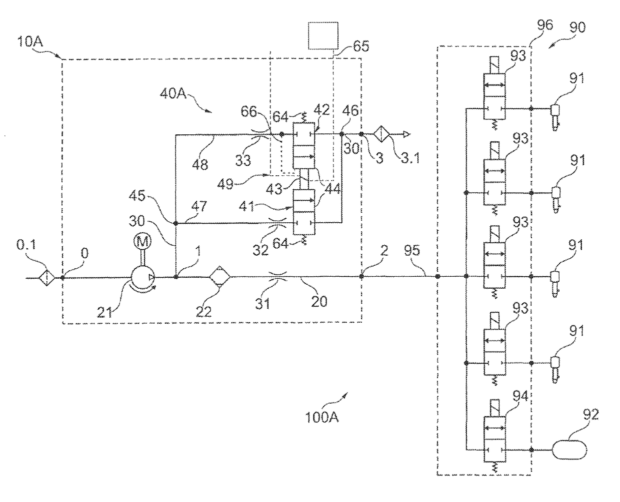
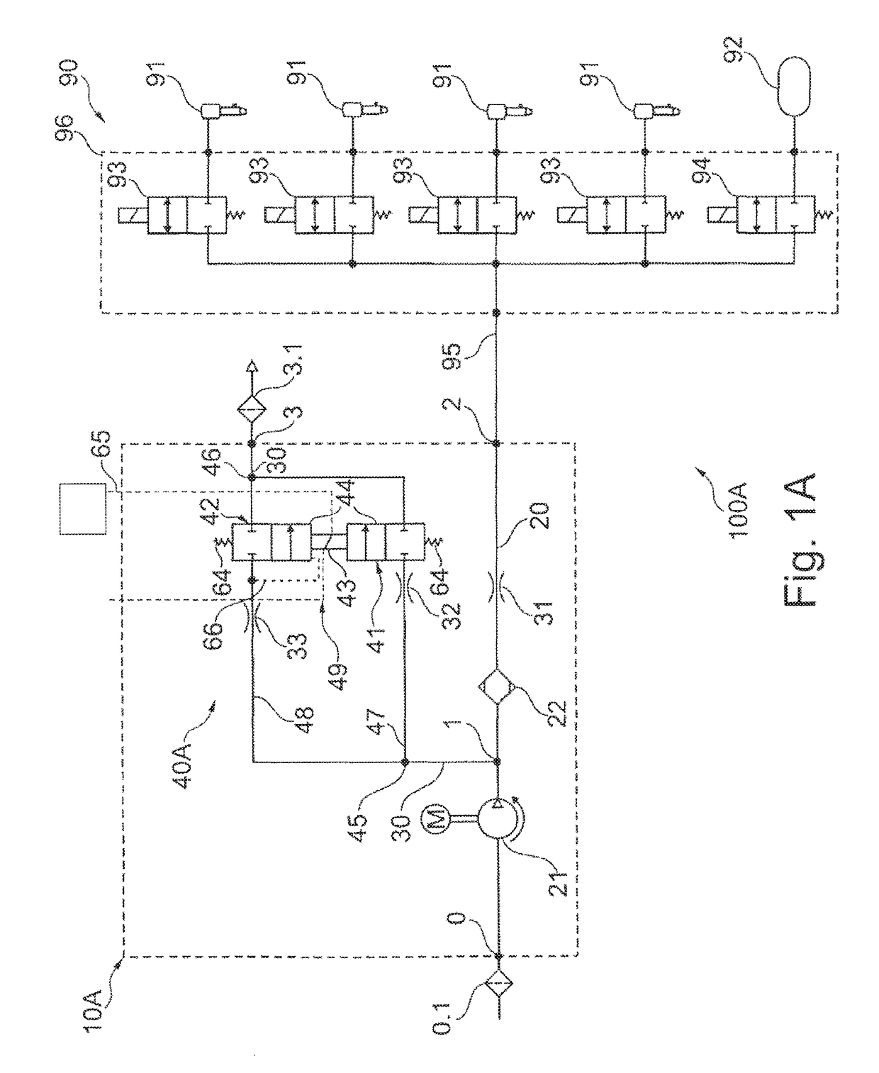
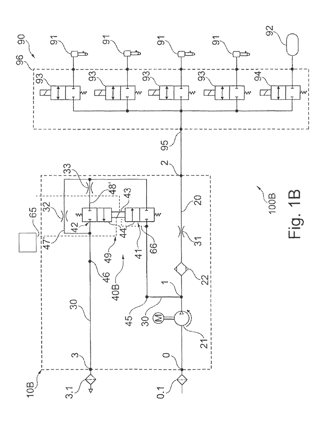
[0123]FIGS. 1A to 1D show, in each case, a pneumatic system 100A, 100B, 100C, 100D with a compressed air supply system 10A, 10B, 10C, 10D and a pneumatic device 90 in the form of a pneumatic spring unit. In the drawing figures, the same designations are expediently used for identical or similar parts, or parts of identical or similar function. The pneumatic spring unit has bellows 91, four in number, which, in each case, are allocated to a wheel of a vehicle, and also an accumulator 92 for the storage of readily available compressed air for the bellows 91. The bellows 91 and the accumulator 92, in the present case in a valve block 96 of five valves, are connected in each case via a normally closed solenoid valve 93, 94—as a bellows valve for the bellows 91 or as an accumulator valve for accumulator 92—to a common pneumatic line, which forms a gallery 95 and which also forms the pneumatic connection between the compressed air supply system 10A, 10B, 10C, 10D and the pneumatic device ...


PUM


Abstract

A compressed air supply installation for operating a pneumatic installation, especially an air suspension installation of a vehicle, includes: an air supply unit and an air compression unit for supplying a compressed air supply unit with compressed air, a pneumatic connection, especially a bleeding line, comprising a bleeding valve system in the form of a controllable solenoid valve system and a bleeding port for bleeding air, and a pneumatic connection, especially a compressed air supply line, comprising an air drier and a compressed air port for supplying compressed air. The solenoid valve system comprises a primary valve and a secondary valve, which are actuatable by a controller of the solenoid valve system that is common to both valves and acts upon both valves.

Description

FIELD OF THE INVENTION[0001]The present invention generally relates to a compressed air supply system and method for operating a pneumatic device.BACKGROUND OF THE INVENTION[0002]Compressed air supply systems are used in vehicles of all types, especially to supply pneumatic spring units with compressed air. Pneumatic spring units can also comprise level control devices, with which the distance between vehicle axle and vehicle body can be adjusted. A pneumatic spring unit of a pneumatic system can comprise a number of air bellows, which are pneumatically connected to a common line (gallery) and can raise the vehicle body as their filling content increases and lower the vehicle body as their compressed air content decreases. With increasing distance between vehicle axle and vehicle body, or ground clearance, the spring deflections become greater and greater, and ground unevenness can also be overcome without contact with the vehicle body occurring. Such systems are used in off-road ve...

Claims


Application Information

Patent Timeline
Patent Type & Authority Patents(United States)
IPC IPC(8): F16F9/02B60G17/015B60G17/052
CPCF16F9/02B60G17/0155B60G17/0523B60G2202/152B60G2600/26B60G2500/2012B60G2500/2021B60G2500/2044B60G2500/30B60G2300/07
Inventor FRANK, DIETERMEISSNER, FRANK
Owner ZF CV SYST EURO BV
Why Eureka
Try Eureka