
Device and method for splicing shielded wire cables

a shielded wire and cable technology, applied in the direction of insulated conductors, cables, unstripped conductor connection apparatus, etc., can solve the problem of complicated interconnection of shielded conductors

Active Publication Date: 2018-03-27
APTIV TECH LTD
View PDF3 Cites 9 Cited by
  • Summary
  • Abstract
  • Description
  • Claims
  • Application Information

AI Technical Summary

Benefits of technology

The patent text describes a wire harness assembly and a method for splicing shielded wire cables together. The wire harness assembly includes a first shielded wire cable with exposed shield conductors and a second shielded wire cable with exposed shield conductors. The assembly also includes a bus bar, a conductive sleeve, and inner and outer insulators. The method involves welding the exposed shield conductors to the bus bar and attaching the inner and outer insulators to the exposed shield conductors. The conductive sleeve is placed over the inner insulator to provide a conductive path between the shield conductors. The wire harness assembly and method provide a reliable and efficient way to connect shielded wire cables.

Problems solved by technology

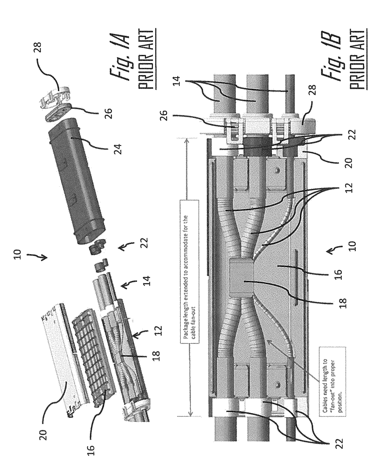
Interconnecting the shield conductors may be complicated because the shield conductors must be cut back from the spliced ends of the cable in order to join the center conductors.

Method used


Image

  • Device and method for splicing shielded wire cables
  • Device and method for splicing shielded wire cables
  • Device and method for splicing shielded wire cables

Examples


Embodiment Construction

[0051]Described herein are devices and a methods for splicing two or more shielded wire cables together. The devices and methods may be used to splice shielded wire cables with a single center conductor, i.e. solid wire, or multiple center connectors, i.e. stranded wire. The devices and methods described herein may also be used to splice two or more shielded wire cables to form a H-splice or Y-splice. The devices and methods described herein may be used for splicing a variety of shielded wire cables types, for example high voltage shielded wire cables designed for electrical or hybrid electrical vehicles.

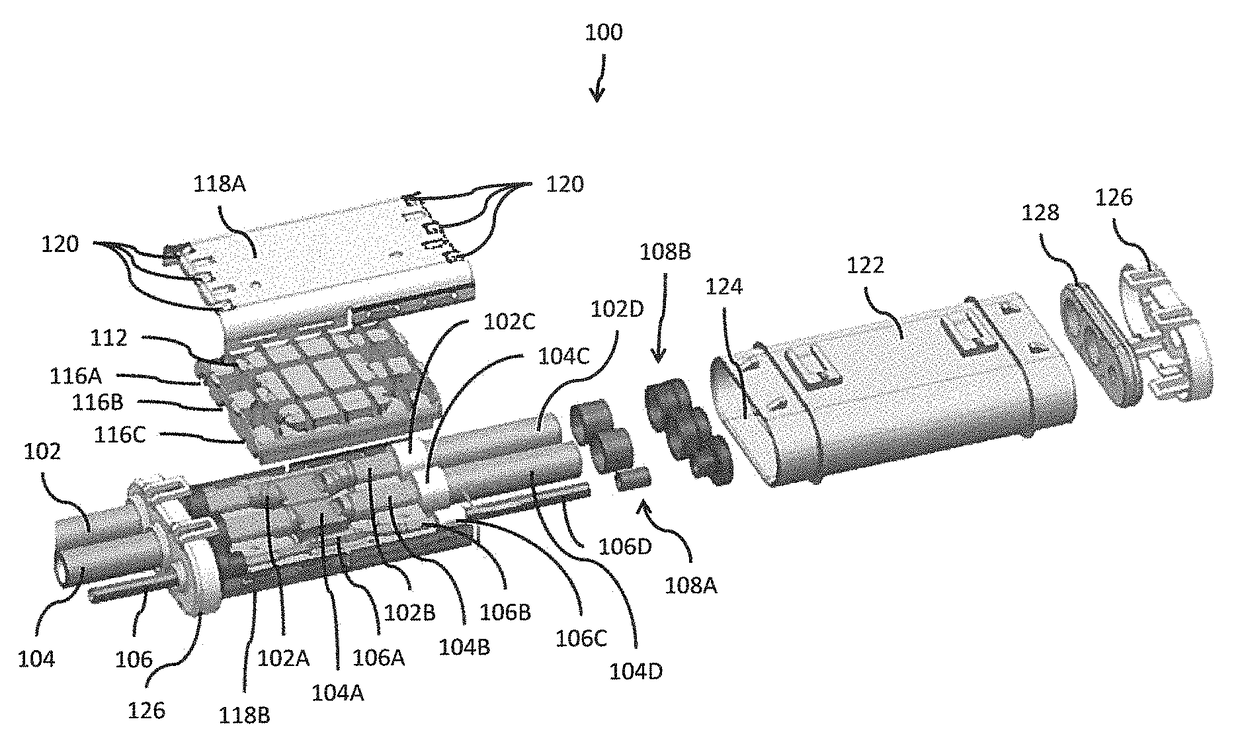
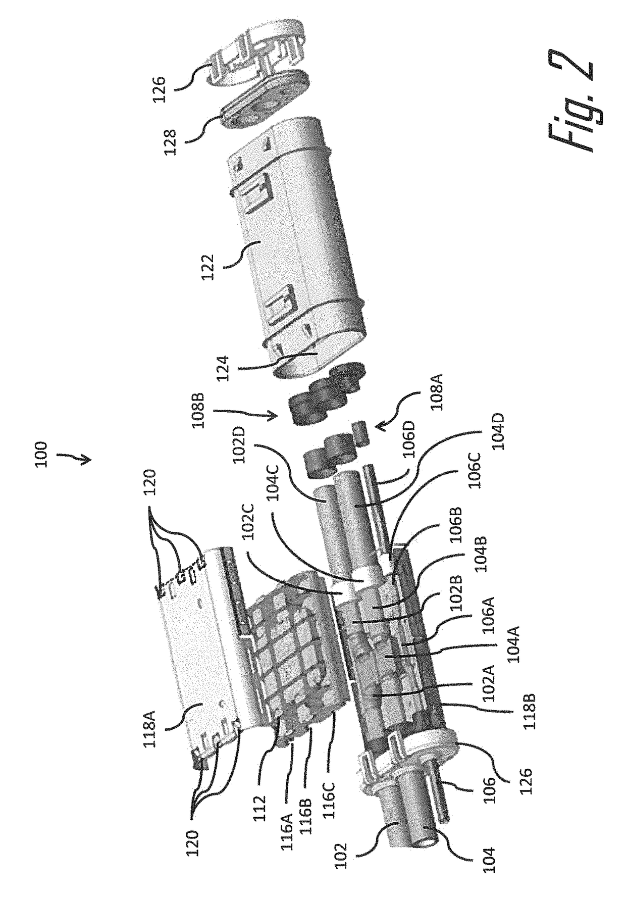
[0052]FIG. 2 illustrates a non-limiting example of a wire harness assembly, hereinafter referred to as the assembly 100 that includes three shielded wire cables 102, 104, 106 that are spliced together in a double H-splice configuration. The assembly 100 includes a device configured to make a splice connection between the three shielded wire cables 102, 104, 106, hereinafter referred...


PUM

PropertyMeasurementUnit
conductiveaaaaaaaaaa
electrically conductiveaaaaaaaaaa
outer diameteraaaaaaaaaa

Abstract

A wire cable assembly, such as those used in electric or hybrid electric vehicles, having a plurality of shielded wire cables that are spliced together is presented. The assembly includes a splicing device having a generally planar bus bar formed of a conductive material, wherein the exposed core conductors of the shielded wire cables are welded to the bus bar, thereby electrically interconnecting the exposed core conductors. A conductive sleeve encloses bus bar and interconnects the shield conductors of the shielded wire cables, providing shielding for the exposed core conductors and continuity for the shield conductors. An outer insulator enclosing the conductive sleeve. A method of splicing shielded wire cables using such a device is also presented herein.

Description

TECHNICAL FIELD OF THE INVENTION[0001]The invention generally relates to a splicing device and a method for joining shielded wire cables.BACKGROUND OF THE INVENTION[0002]Shielded wire cables typically include an insulated center conductor and a separate insulated shield conductor surrounding the center conductor insulation. The shield conductor may consist of a braided wire mesh, metal foil, or metalized film. The cables typically have a second insulation layer covering the shield conductor. Shielded wire cables have been long used for communications systems, such as in cable television transmission lines. Shielded wire cables are also finding use in high voltage applications in electric and hybrid electric vehicles. When shielded wire cables are spliced together, there is usually a need to electrically connect the shield conductors of the spliced cables as well as the center conductor, in order to maintain electrical continuity of the shield conductors. Interconnecting the shield c...

Claims


Application Information

Patent Timeline
Patent Type & Authority Patents(United States)
IPC IPC(8): H01B7/00B60R16/02H01B13/012H02G15/18H01R9/03H01R43/02H01R43/01H01R9/24H01R4/02
CPCH01B7/0045H01R4/029H01R9/2483H01R9/031H01R43/02H01R43/01H01R43/0263H02G15/18H01B13/01209B60R16/0215H01R4/021H01R4/70H02G15/1055H01R2201/26
Inventor VOLPONE, THOMAS A.ILER, TROY A.
Owner APTIV TECH LTD
Learn More