
Spectrally-engineered solar thermal photovoltaic devices

a solar thermal and photovoltaic technology, applied in the field of solar thermal photovoltaic devices, can solve the problems of spectral control and the difficulty of efficient sunlight collection, and achieve the effects of reducing parasitic radiation, reducing heat conducted away and lost, and lowering operating temperatures

Inactive Publication Date: 2018-03-27
MASSACHUSETTS INST OF TECH
View PDF8 Cites 1 Cited by
  • Summary
  • Abstract
  • Description
  • Claims
  • Application Information

AI Technical Summary

Problems solved by technology

However, since power generation using PVs is intermittent and typically only utilizes a portion of the solar spectrum efficiently, and the solar thermal approach is best suited for utility-scale power plants, there is an imminent need for hybrid technologies.
However, the need for high operating temperatures of the devices makes spectral control and the efficient collection of sunlight particularly challenging, limiting prior experimental demonstrations to solar-to-electrical conversion efficiencies around 1% or below.

Method used


Image

  • Spectrally-engineered solar thermal photovoltaic devices
  • Spectrally-engineered solar thermal photovoltaic devices
  • Spectrally-engineered solar thermal photovoltaic devices

Examples


example 1

[0027]As shown in FIG. 5, the output power of the PV cell displays an exponential behavior as Planck's distribution shifts to higher energies with increasing emitter temperature. These experimental results are supported by a spectral quasi-1D diffuse radiative network model (SQ1DD). The model assumes isothermal operation of the absorber-emitter module (i.e., Ta=Te=Tae) and accounts for the experimentally measured spectral properties of the components (e.g., ϵλ, IQE) and the geometrical configuration of the planar solar thermal photovoltaic device. The results of the thermal PV experiment serve as a validation of the model and provide an indirect method for determining the temperature of the absorber-emitter module from the measured output power. This approach was used in the solar thermal photovoltaic device characterization since a direct in-situ measurement of the absorber-emitter module temperature with minimal impact on the efficiency was challenging.

example 2

[0028]The full energy conversion processes were investigated in the solar thermal photovoltaic device with increasing emitter-to-absorber area ratios. FIG. 6A shows the electrical output power of the solar thermal photovoltaic devices as a function of irradiance (Hs) and the absorber-emitter temperature (determined using the relation between pout and Tae shown in FIG. 5) for various emitter-to-absorber area ratios. In FIGS. 6A-D, the markers shown are experimental points (errors bars represent 95% confidence interval), and the solid bands represent the SQ1DD model. The upper and lower estimates of the SQ1DD model associated with treating Hs as collimated or diffuse, respectively, bound the data within the experimental uncertainty. In FIG. 6A, the effect of increasing AR is manifested in shifting the operating points to a regime of increased irradiance (Hs) relative to the thermal re-emission loss (σTae4). If the absorber solar collection efficiency is considered (a major component o...


PUM


Abstract

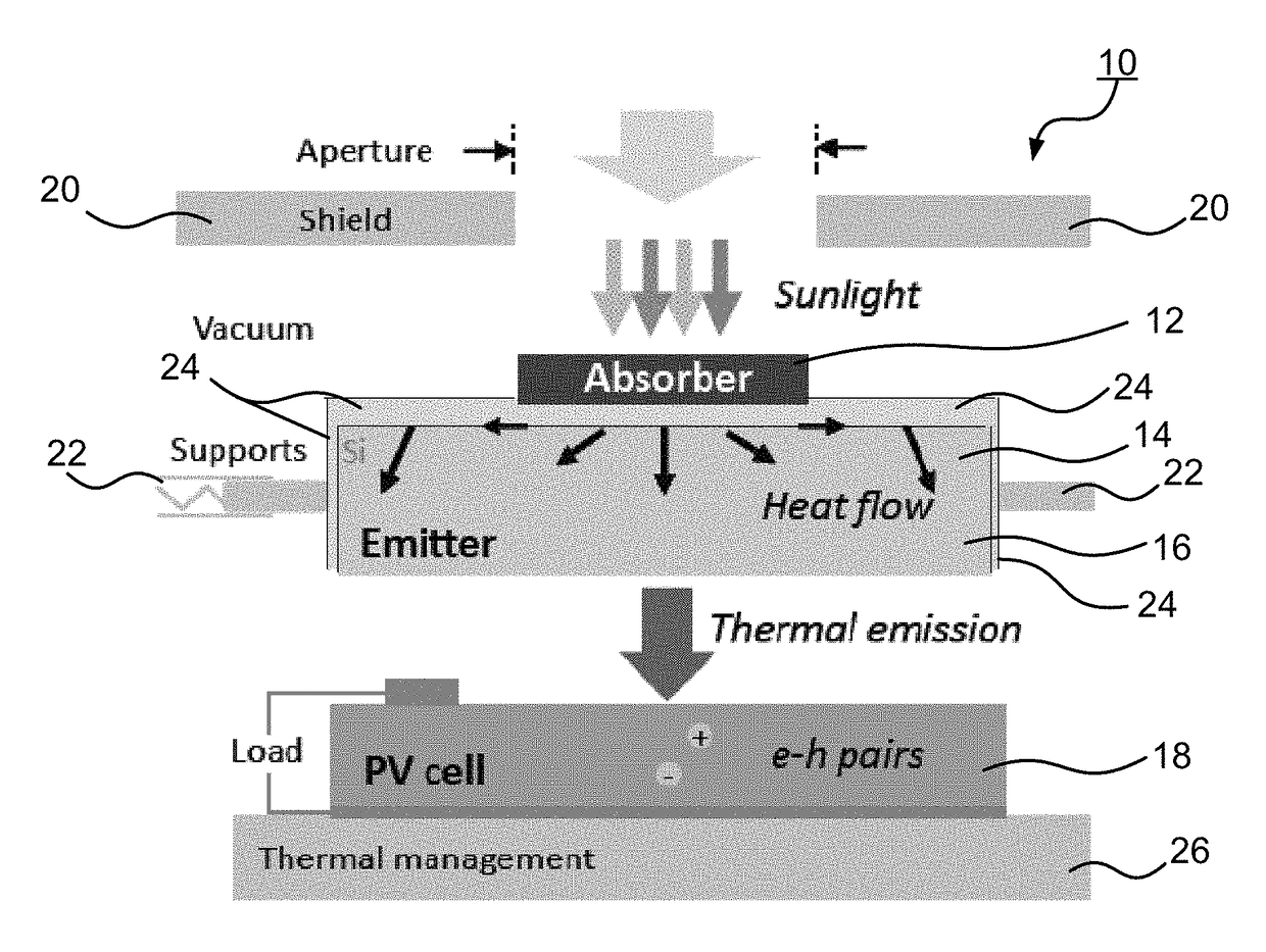
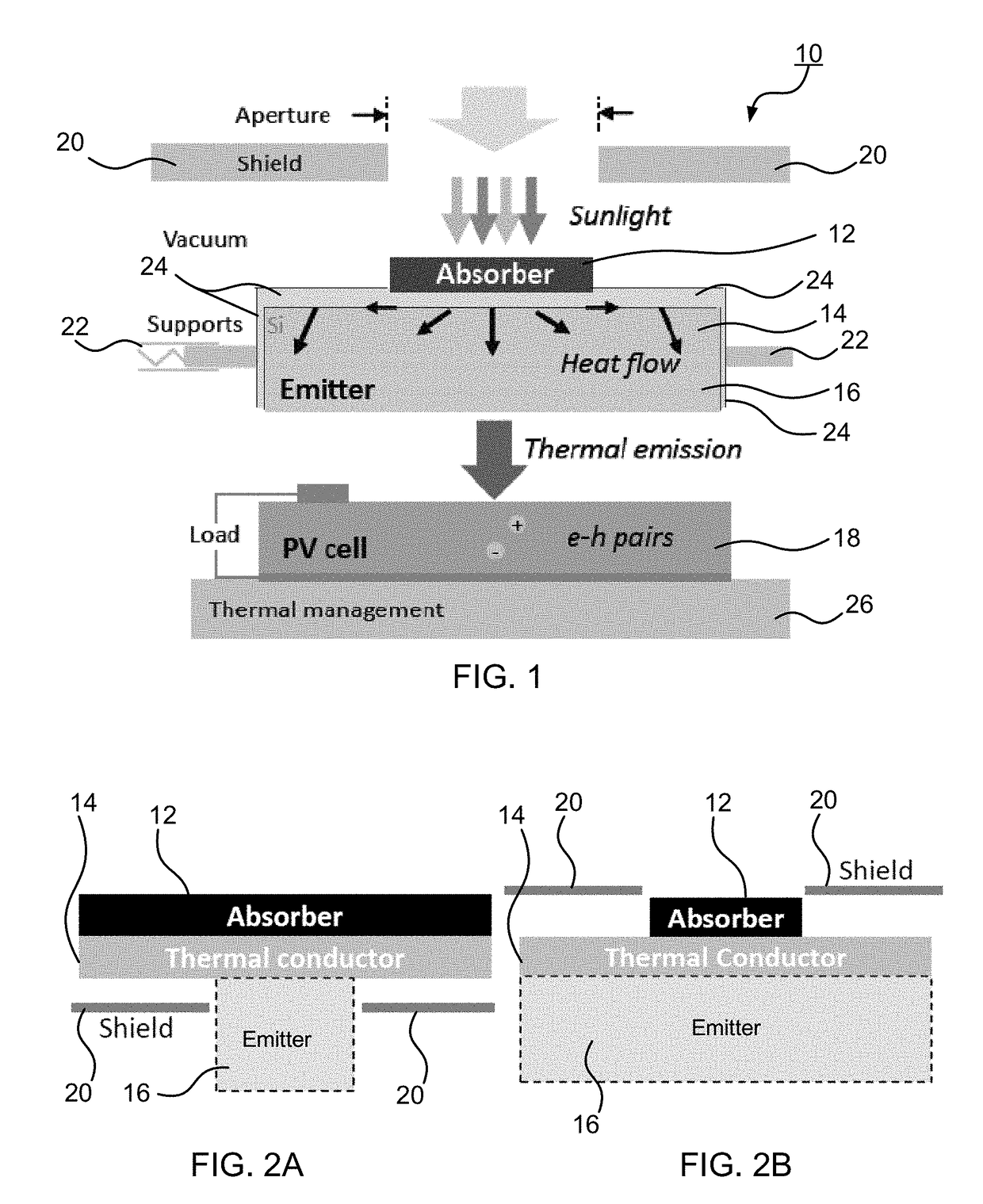
A solar thermal photovoltaic device, and method of forming same, includes a solar absorber and a spectrally selective emitter formed on either side of a thermally conductive substrate. The solar absorber is configured to absorb incident solar radiation. The solar absorber and the spectrally selective emitter are configured with an optimized emitter-to-absorber area ratio. The solar thermal photovoltaic device also includes a photovoltaic cell in thermal communication with the spectrally selective emitter. The spectrally selective emitter is configured to permit high emittance for energies above a bandgap of the photovoltaic cell and configured to permit low emittance for energies below the bandgap.

Description

CROSS-REFERENCE TO RELATED APPLICATIONS[0001]This patent application claims the benefit of U.S. Provisional Patent Application No. 61 / 898,083 filed Oct. 31, 2013, the disclosure of which is incorporated by reference herein in its entirety.STATEMENT REGARDING FEDERALLY SPONSORED RESEARCH OR DEVELOPMENT[0002]This invention was made with Government support under Contract Nos. DE-SC0001299 and DE-FG02-09ER46577 awarded by the Department of Energy and under Contract No. W911NF-13-D-0001 awarded by the Army Research Office. The Government has certain rights in the invention.TECHNICAL FIELD[0003]The present invention relates to photovoltaic devices, and more specifically to solar thermal photovoltaic devices.BACKGROUND ART[0004]To generate power from sunlight, the most common approaches are either photovoltaic (PV), where sunlight directly excites electron-hole pairs, or solar thermal, where sunlight drives a mechanical heat engine. However, since power generation using PVs is intermittent...

Claims


Application Information

Patent Timeline
Patent Type & Authority Patents(United States)
IPC IPC(8): H02S10/30H01L31/0216
CPCH01L31/02164H02S10/30Y02E10/50
Inventor LENERT, ANDREJBIERMAN, DAVIDCHAN, WALKERCELANOVIC, IVANSOLJACIC, MARINWANG, EVELYN N.NAM, YOUNG SUKMCENANEY, KENNETHKRAEMER, DANIELCHEN, GANG
Owner MASSACHUSETTS INST OF TECH
Learn More