Intervertebral prosthesis, apparatus for implanting intervertebral prostheses and surgical method for implanting intervertebral prostheses, particularly for percutaneous minimally-invasive surgical procedures

Inactive Publication Date: 2018-04-03
REDEMED
View PDF12 Cites 0 Cited by
  • Summary
  • Abstract
  • Description
  • Claims
  • Application Information

AI Technical Summary

Benefits of technology

[0044]Preferably, the at least one insertion instrument has, at said distal part thereof, a threaded shank that can engage a threaded hole, which is defined in said intervertebral prosthesis at a side wall of said intervertebral prosthesis substantially coaxially to a through-hole that passes through said intervertebral prosthesis from side to side along a direction p

Problems solved by technology

Some of these disorders produce a degeneration of the fibrous capsule of the intervertebral disc, which reduces its elasticity and becomes damaged, allowing part of the nucleus pulposus to escape.
This thinning often also produces the thinning of the facet capsules, with consequent pain.
In some cases, this thinning can lead to the reduction of the medullary canal, with a severe risk of chronic claudication.
This type of conventional intervertebral prosthesis, which is generally applied at the level of the lumbar vertebrae, which are the ones subjected to the greatest load determined by body weight, is not free from drawbacks, which include the fact that generally it requires an extremely invasive surgical procedure for implantation.
It should be stressed that this surgical procedure, in addition to being inherently laborious and time-consuming, can lead to severe consequences for the patient since, although the procedure is monitored at the neurological level by a device that detects if there is a nervous structure proximate to the surgical instrument, it does not allow the surgeon to detect and therefore monitor the compression of tissues and muscles (against the transverse apophyses) caused by the divarication or expansion of the retractor instrument, which very often leads to the stretching and/or compression of the femoral plexus throughout the duration of the procedure.
Anoth

Method used


Image

  • Intervertebral prosthesis, apparatus for implanting intervertebral prostheses and surgical method for implanting intervertebral prostheses, particularly for percutaneous minimally-invasive surgical procedures
  • Intervertebral prosthesis, apparatus for implanting intervertebral prostheses and surgical method for implanting intervertebral prostheses, particularly for percutaneous minimally-invasive surgical procedures
  • Intervertebral prosthesis, apparatus for implanting intervertebral prostheses and surgical method for implanting intervertebral prostheses, particularly for percutaneous minimally-invasive surgical procedures

Examples


Embodiment Construction

[0099]As required, detailed embodiments of the present invention are disclosed herein; however, it is to be understood that the disclosed embodiments are merely exemplary of the invention that may be embodied in various and alternative forms. The figures are not necessarily to scale; some features may be exaggerated or minimized to show details of particular components. Therefore, specific structural and functional details disclosed herein are not to be interpreted as limiting, but merely as a representative basis for teaching one skilled in the art to variously employ the present invention.

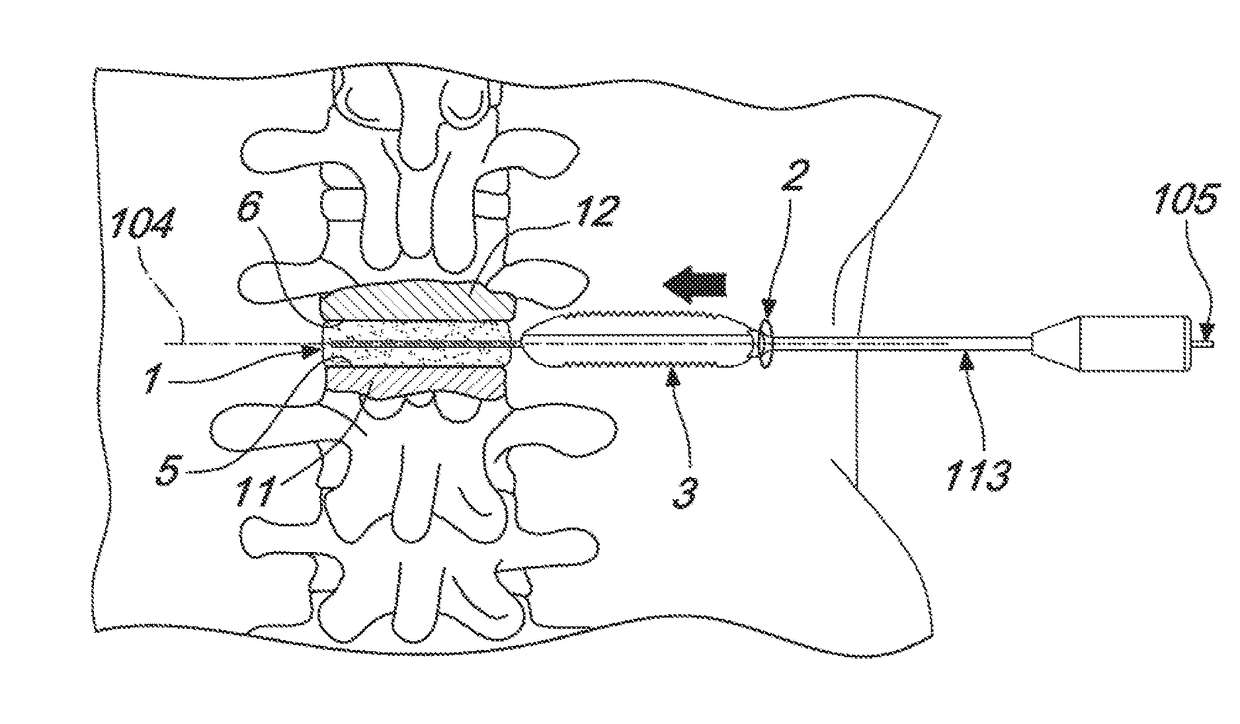
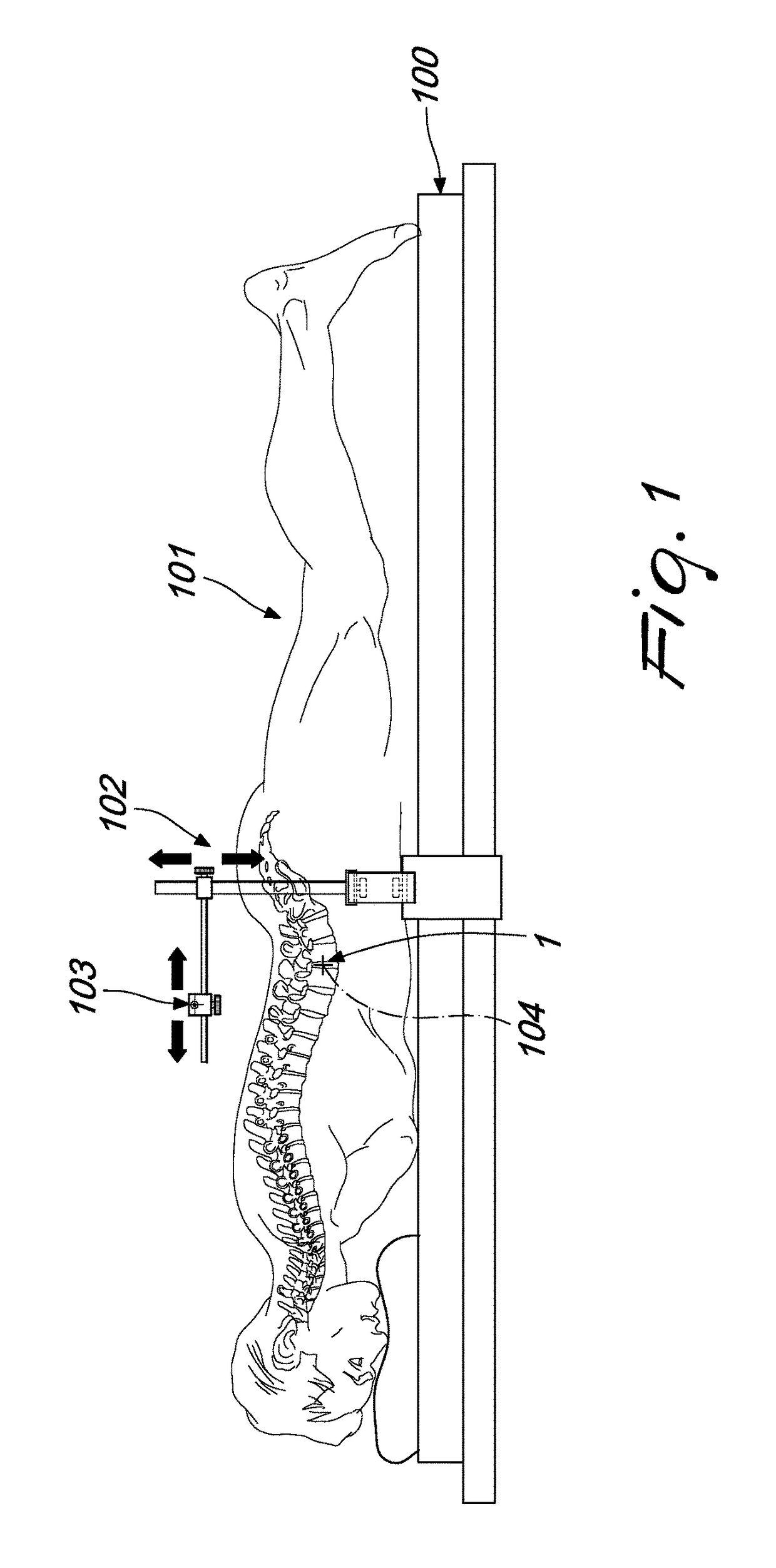
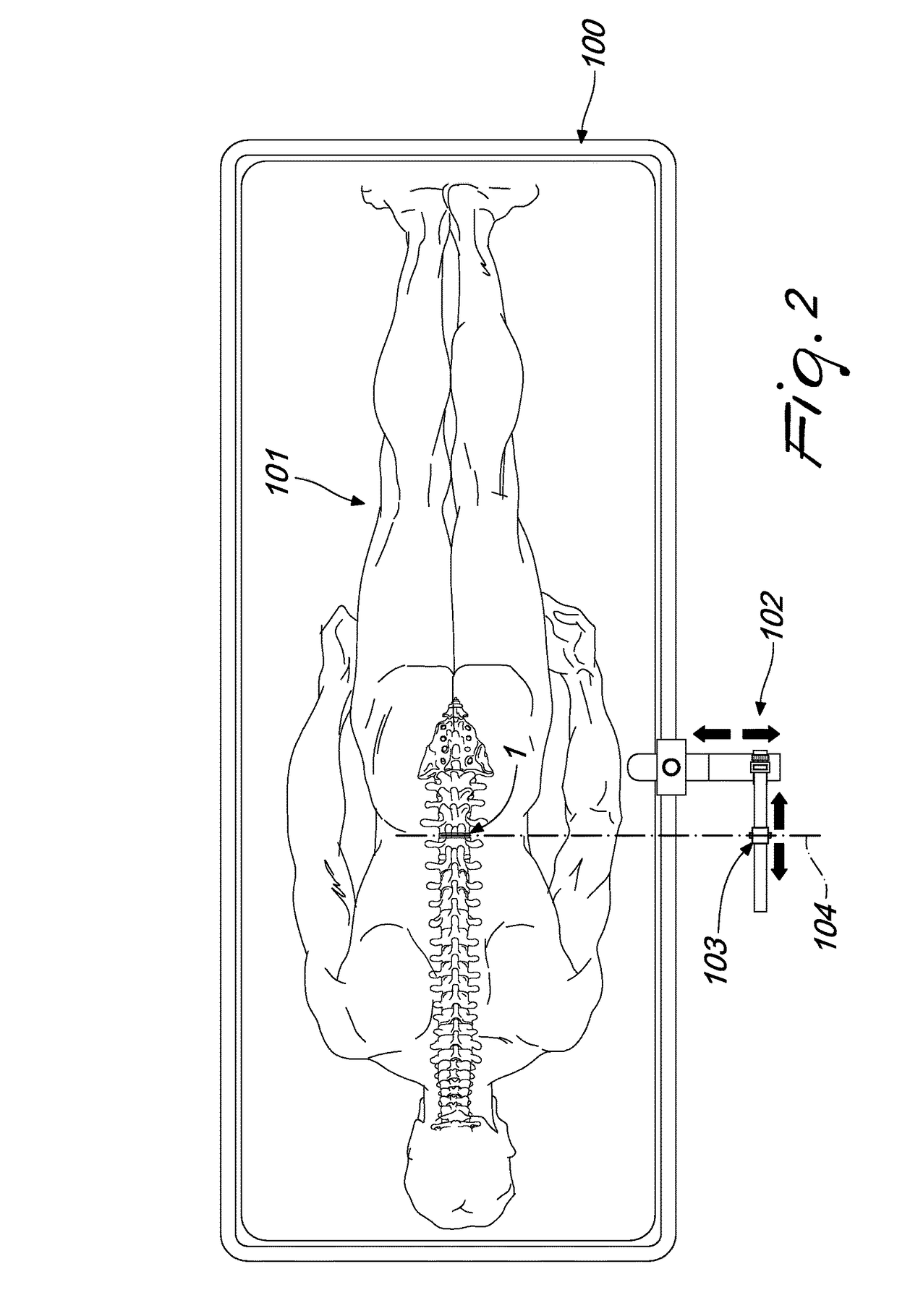
[0100]With reference to the figures, the surgical method for implanting intervertebral prostheses, particularly for percutaneous minimally-invasive surgical procedures, comprises first of all the placement on an operating table 100 of a patient 101 to be operated on, preferably in a prone position.

[0101]Then a first radiograph is performed by way of a radiological device, not shown for the sake o...


PUM


Abstract

An intervertebral prosthesis, particularly for percutaneous minimally-invasive surgery having a substantially disc-like geometry with a thickness equal to the intervertebral distance to be restored is provided. In a lateral elevation view, in the intervertebral prosthesis there is a through-hole adapted to allow its sliding along a guiding wire inserted previously in the patient through a percutaneous minimally-invasive anterolateral access.

Description

TECHNICAL FIELD[0001]The present application relates to an intervertebral prosthesis, particularly for percutaneous minimally-invasive surgical procedures, and to the apparatus and surgical method for implanting the intervertebral prosthesis.BACKGROUND[0002]Numerous disorders affecting the spinal column and in particular affecting the intervertebral discs are currently known in medicine.[0003]Some of these disorders produce a degeneration of the fibrous capsule of the intervertebral disc, which reduces its elasticity and becomes damaged, allowing part of the nucleus pulposus to escape.[0004]This phenomenon is commonly known as “hernia”.[0005]There are also other disorders, of a progressive type, which entail the thinning, over time, of the intervertebral disc owing to the loss of its ability to retain water inside it. This thinning often also produces the thinning of the facet capsules, with consequent pain.[0006]In some cases, this thinning can lead to the reduction of the medullar...

Claims


Application Information

Patent Timeline
IPC IPC(8): A61F2/44A61B17/88A61F2/46A61B17/16
CPCA61F2/4611A61B17/1659A61B17/1671A61F2/442A61F2/4455A61F2/4465A61F2/4657A61F2002/4677A61F2002/4475A61F2002/4627A61F2002/4629A61F2002/4635A61F2002/4661A61B2017/0256A61B90/10A61B90/11A61B90/50A61B2090/508A61F2002/30593
Inventor TARRICONE, LUIGIANTONELLI, LUCA
Owner REDEMED
Why Eureka
Try Eureka