Electric fin stabilizer

a stabilizer and electric fin technology, applied in the direction of process and machine control, vessel movement reduction by foils, instruments, etc., can solve the problems of system overheating, difficult installation and maintenance, and increase the cost of the system, so as to avoid the use of expensive and complicated hydraulics, the effect of easy installation and maintenan

Active Publication Date: 2018-04-17
NAIAD MARITIME GRP
View PDF35 Cites 9 Cited by
  • Summary
  • Abstract
  • Description
  • Claims
  • Application Information

AI Technical Summary

Benefits of technology

[0010]It is therefore an object of the invention to provide a fin roll stabilizer that avoids use of expensive and complicated hydraulics and allows for easy installation and maintenance while still fitting in tight spaces of vessel hulls.
[0011]It is another object of the invention to provide a manual locking system that allows the position of the fins to be placed in a fixed and neutral position in the event of a failure.
[0014]These and other objects are achieved by providing a marine vessel stabilizer and control system including a fin having a stem extending into the hull. An arm is connected to an end of the stem and extends towards a connector. The connector is connected to one end of a rod. A housing is connected to another end of the rod and a screw passes through the housing such a hollow section of the rod is arranged concentrically around the screw. A motor is connected to the screw and configured to rotate to thereby rotate the fin. A controller is connected to the motor, a speed sensor, a roll sensor and a fin position sensor such that a control signal can be calculated and the position of the fin can be determined to reduce roll of the vessel both when making headway and when at rest.

Problems solved by technology

In order to create a functioning stabilizing system, a complicated setup of hydraulic plumbing, valves, cylinders and pumps are needed to operate and control the stabilizer.
The hydraulic system components all need connection with hose or pipe which can run long distances within a vessel and be difficult to install and require maintenance.
The hydraulic system also comes with added environmental concerns associated with hydraulic oil because a leak in the system can bleed in to the bilge of the vessel and be pumped out with bilge water into the ocean or other body of water where the marine vessel is operating.
This adds cost to the system.
In addition, air in the hydraulic system can cause control problems and when the air bubbles collapse they generate intense localized heat in the hydraulic oil leading to system overheating and early hydraulic component failure.
Air in the system can also cause objectionable noise and vibration transmitted throughput the vessel via the interconnecting hydraulic piping.
Another concern of a shipboard hydraulic system is fire.
At higher pressures the hydraulic system is more prone to leaks and when a leak occurs the oil can mist or spray onto hot surfaces in the vessel's machinery spaces or be vaporized, and when exposed to a source of ignition vaporized oil causes fire.
Stabilizer fins often require high torque to operate such that a direct drive motor needs to be relatively large and heavy.
A reduction gear between the motor and fin would reduce the motor size, but the gear arrangement and motor together adds a significant height to the stabilizer and may not fit in the confined space within the hull.
In addition, failure of part of the stabilizer system can result in a crippled vessel because the fins may be in fixed positions that make it difficult to move the vessel under power.
For example, if the fin is at 20 degrees to the lengthwise axis of the vessel, moving the vessel through the water will cause an un-desired list and fin drag when under power.

Method used


Image

  • Electric fin stabilizer
  • Electric fin stabilizer
  • Electric fin stabilizer

Examples


Embodiment Construction

[0034]Referring now to the drawings, wherein like reference numerals designate corresponding structure throughout the views. The following examples are presented to further illustrate and explain the present invention and should not be taken as limiting in any regard.

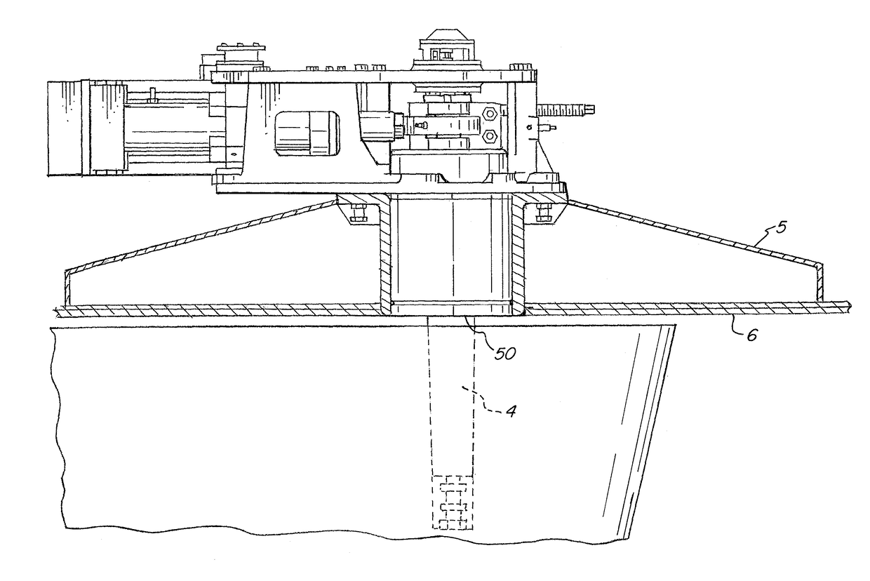
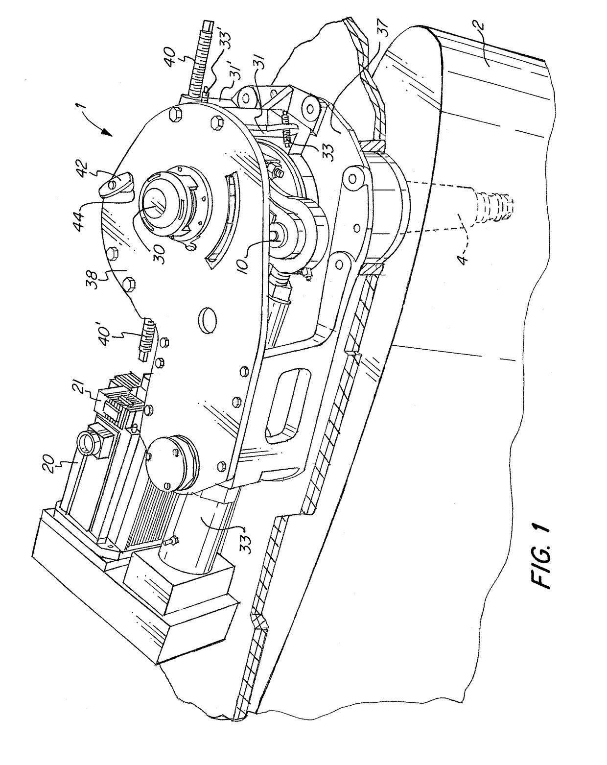
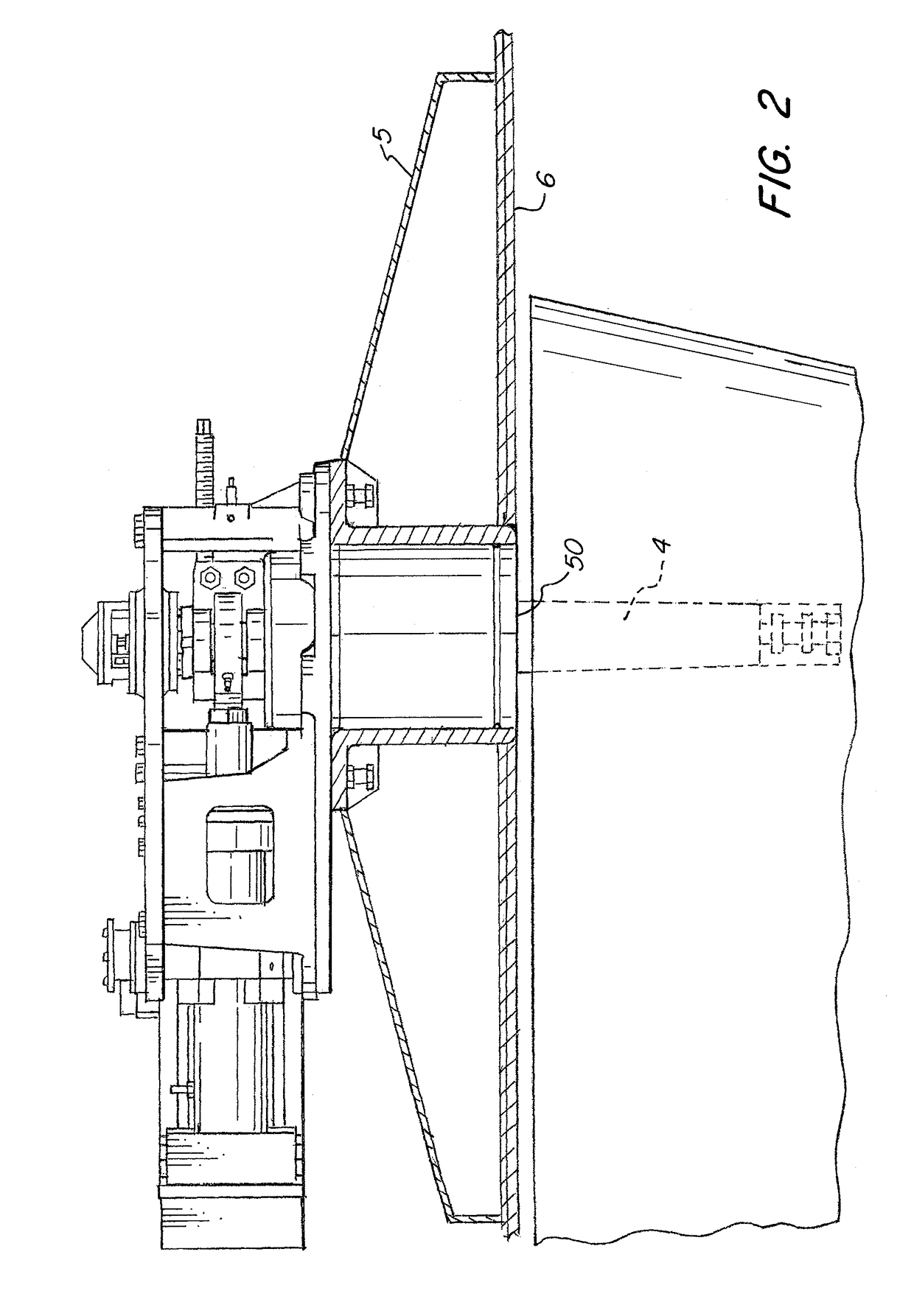
[0035]The stabilizer 1 includes a fin 2 that is installed on the outside of the vessel hull 6. The fin is generally installed in the hull below the waterline usually near the turn of the bilge such that rotation of the fin in the water creates a roll moment acting on the marine vessel that counteracts roll of the marine vessel due to conditions of the body of water in which the vessel is operating. As shown in FIG. 6, the plane of fin 2 is mounted normal to the hull, but other mounting angles are contemplated. As can be understood in FIG. 6, the stem 4 is approximately perpendicular to the lengthwise axis of the vessel when viewed from the side, but need not be depending on hull shape or other factors. As but one exampl...


PUM


Abstract

A marine vessel stabilizer and control including a fin having a stem extending into the hull. An arm is connected to the stem and extends towards a connector which is connected to a rod. A housing is connected to another end of the rod and a screw passes through the housing. A motor is connected to the screw and configured to rotate to rotate the fin. A controller is connected to the motor, a speed sensor, a roll sensor and a fin position sensor such that a control signal can be calculated and the position of the fin can be determined to reduce roll of the vessel both when making headway and when at rest (zero speed). When the vessel is at rest, the fin is be configured to rotate through maximum angles greater than 15 degrees from either side of a neutral position.

Description

FIELD OF THE INVENTION[0001]The invention relates to stabilizers and control systems for stabilizers that are used for marine vessels both when making headway and at rest (e.g. zero speed).BACKGROUND OF THE INVENTION[0002]Fin roll stabilizers are commonly mounted to the bottom of a vessel below the waterline, usually close to the turn of the bilge. These fins rotate about an axis that is perpendicular to the lengthwise axis of the vessel. The stabilizers are generally aligned parallel to the lengthwise axis of the vessel and rotation of these fins reduces roll of the vessel. The fin roll stabilizers act in some ways that are similar to ailerons on an airplane.[0003]Traditional fin roll stabilizers for marine vessels are powered hydraulically. In order to create a functioning stabilizing system, a complicated setup of hydraulic plumbing, valves, cylinders and pumps are needed to operate and control the stabilizer. In addition, a reservoir must be provided to supply the pumps with hyd...

Claims


Application Information

Patent Timeline
Patent Type & Authority Patents(United States)
IPC IPC(8): B63B39/06G05D1/08
CPCG05D1/0875B63B39/06
Inventor VENABLES, JOHN D.PAPPAS, CHRISTOPHER M.
Owner NAIAD MARITIME GRP
Why Eureka
Try Eureka