
Portable heating arrangement

a heating arrangement and portable technology, applied in the direction of heater elements, ohmic-resistance heating, snow traps, etc., can solve the problems of affecting the operation of the heating device, etc., to achieve convenient installation, convenient portability and storage, and easy removal.

Inactive Publication Date: 2018-04-17
AMANTE RADIANT SUPPLY
View PDF66 Cites 1 Cited by
  • Summary
  • Abstract
  • Description
  • Claims
  • Application Information

AI Technical Summary

Benefits of technology

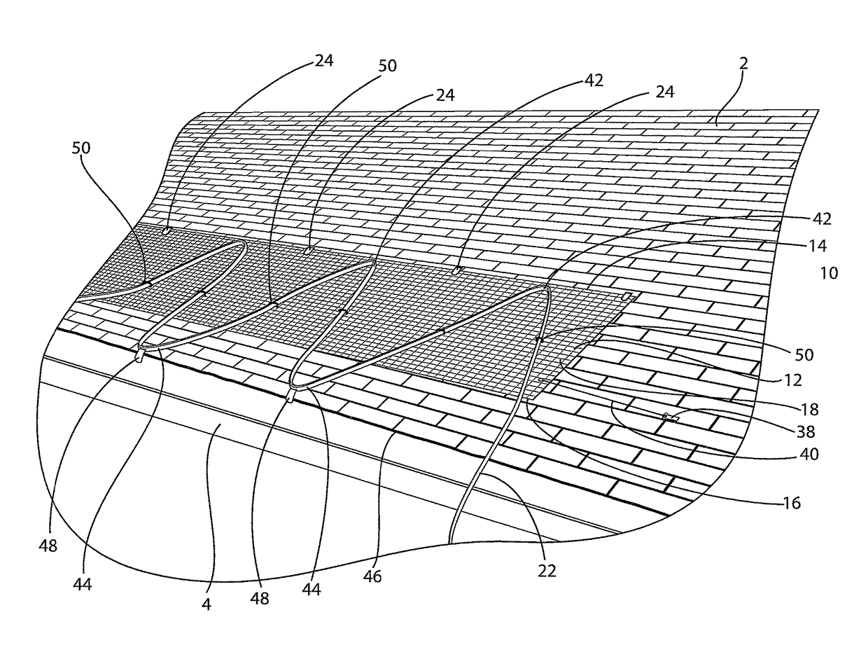
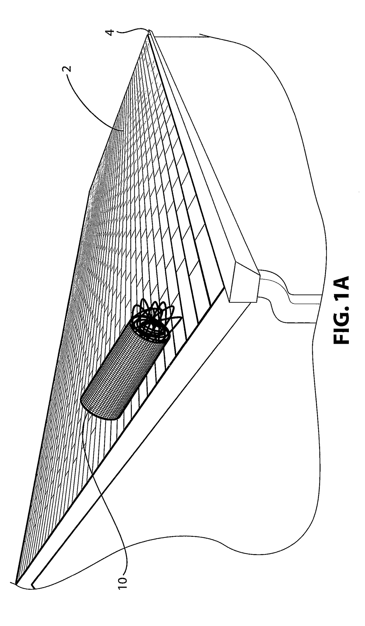
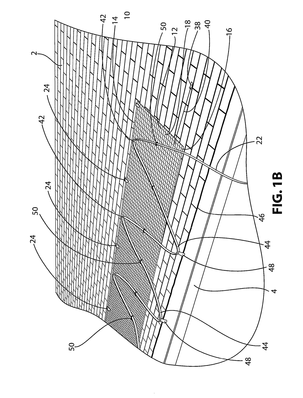
[0012]Accordingly, the present invention provides a heating arrangement for providing heat to a surface that overcomes some or all of the drawbacks and deficiencies identified above, in connection with conventional permanently-installed heating systems. Preferably, the present invention provides a heating arrangement that can be easily installed by a property owner without needing a roofer or an electrician to perform the work. Preferably, the present invention provides a heating arrangement that is easily removable from the roof and gutter and, once removed, is easily portable and storable. By making the system easily portable, the property owner can take down the heating cables during times of the year when the system is not in use (e.g., spring, summer, and autumn), thereby reducing the amount of UV radiation that the cables are exposed to during the year and reducing the times during the year when the unsightly system is in place. Preferably, the present invention provides a heating arrangement that can be installed in a relatively inexpensive manner and will continue to provide effective heat to the surface for many years.
[0016]In certain preferred and non-limiting configurations, the ties for connecting the heating conduit to the base comprise a releasable lock, such that the ties can be disconnected from the base, moved to a different location on the base, and reconnected to the base so that the pattern of the heating conduit can be modified. In certain preferred and non-limiting configurations, the arrangement further includes a track extending along an upper edge of the base, where the connectors may be slidably mounted along the track, so that the connectors can be moved along the upper edge of the base.

Problems solved by technology

Accumulation of ice and snow on roofs and in rain gutters presents a variety of problems for property owners.
For example, accumulated ice and snow apply pressure against a roof and gutter which, over time, weakens the structure.
Furthermore, accumulated ice and snow may thaw and freeze many times over the course of the winter permitting water to collect in cracks and to expand during freezing, further weakening the roof and gutter structure.
Additionally, accumulated ice and snow may block gutters.
As a result, during rainstorms the gutter overflows causing water damage to the building or property.
Further still, accumulated ice and snow can cause rust, damaging metal portions of a roof or gutter and causing the structure to degrade prematurely.
When a user becomes concerned that snow and ice is accumulating, the user turns on the system causing the cables to heat up, thereby melting the snow and ice.
Self-regulating cables tend to be more durable than constant wattage cables, but are also more expensive.
The installation process tends to be a time consuming and rather labor intensive process.
Most significantly, such permanent systems are expensive as a result of both the cost of the cables themselves, which can be several hundred dollars, and the labor intensive installation process.
In addition, the useful life of the heating system is limited by the lifespan of the cable.
Furthermore, while wear and tear caused by snow and ice accounts for some of the degradation of the installed systems, the greatest impact on the lifespan of the cables is from prolonged exposure to solar ultraviolet (UV) radiation, which breaks down the rubber or synthetic polymer casing surrounding the cable.
Continual heating and cooling of the cable also causes the wires to swell and contract over time, which weakens the clips and roof shingles.
Thus, exposure to the elements during the summer months, when UV levels and temperature are higher, contributes to the breakdown of the heating cables as much as exposure to ice and snow during winter.
Blockage of gutters is especially problematic during spring and autumn, when dead leaves and vegetation are most likely to accumulate on roof surfaces.

Method used


Image

  • Portable heating arrangement
  • Portable heating arrangement
  • Portable heating arrangement

Examples


Embodiment Construction

[0034]For purposes of the description hereinafter, the teens “upper”, “lower”, “right”, “left”, “vertical”, “horizontal”, “top”, “bottom”, “lateral”, “longitudinal” and derivatives thereof shall relate to the invention as it is oriented in the drawing figures. Similarly, as used herein, the term “below” refers to the downward direction, as depicted in the drawing figures. However, it is to be understood that the invention may assume various alternative variations, except where expressly specified to the contrary. It is also to be understood that the specific devices and processes illustrated in the attached drawings, and described in the following specification, are simply exemplary embodiments of the invention. Hence, specific dimensions and other physical characteristics related to the embodiments disclosed herein are not to be considered as limiting.

[0035]The present invention is a portable heating arrangement 10 for providing heat to a surface 2, such as a synthetic shingle, woo...


PUM

PropertyMeasurementUnit
heataaaaaaaaaa
volumeaaaaaaaaaa
angleaaaaaaaaaa

Abstract

A portable heating arrangement for providing heat to a surface, such as a roof and rain gutter is provided. The portable heating arrangement includes a base configured to rest upon the surface and at least one heating conduit directly or indirectly mounted to at least a portion of the base and configured to provide heat to the surface. The heating arrangement may further include at least one connector configured to directly or indirectly attach at least a portion of the base to the surface. The heating conduit may include a metal wire enclosed within a conductive core and polymer sheath. A method of forming a portable heating arrangement and a method for heating a surface are also provided herein.

Description

CROSS REFERENCE TO RELATED APPLICATIONS[0001]This application claims the benefit of U.S. Provisional Patent Application No. 61 / 711,904 entitled “Portable Heating Arrangement” filed Oct. 10, 2012, which is hereby incorporated by reference in its entirety.BACKGROUND OF THE INVENTION[0002]Field of the Invention[0003]The present invention relates generally to devices and arrangements of devices for heating surfaces and, in particular, to a portable heating arrangement including a heating conduit extending across a surface, such as a roof, and / or through a trough or channel, such as a rain gutter, for the purpose of preventing the buildup of ice and snow.[0004]Description of Related Art[0005]Accumulation of ice and snow on roofs and in rain gutters presents a variety of problems for property owners. For example, accumulated ice and snow apply pressure against a roof and gutter which, over time, weakens the structure. Furthermore, accumulated ice and snow may thaw and freeze many times ov...

Claims


Application Information

Patent Timeline
Patent Type & Authority Patents(United States)
IPC IPC(8): H05B3/34H05B3/06E04D13/10
CPCH05B3/34E04D13/103H05B3/06Y10T29/49826H05B2214/02
Inventor WHITCRAFT, JOSH
Owner AMANTE RADIANT SUPPLY
Learn More