PZT-film laminated structure, liquid discharge head, liquid discharge device, liquid discharge apparatus, and method of making PZT-film laminated structure

Active Publication Date: 2018-04-24
RICOH KK
View PDF22 Cites 6 Cited by
  • Summary
  • Abstract
  • Description
  • Claims
  • Application Information

AI Technical Summary

Problems solved by technology

However, in each of the production methods, impurities of raw materials are considered to act as disturbance factors to the target functions of the materials.

Method used


Image

  • PZT-film laminated structure, liquid discharge head, liquid discharge device, liquid discharge apparatus, and method of making PZT-film laminated structure
  • PZT-film laminated structure, liquid discharge head, liquid discharge device, liquid discharge apparatus, and method of making PZT-film laminated structure
  • PZT-film laminated structure, liquid discharge head, liquid discharge device, liquid discharge apparatus, and method of making PZT-film laminated structure

Examples


example 1

[0144]

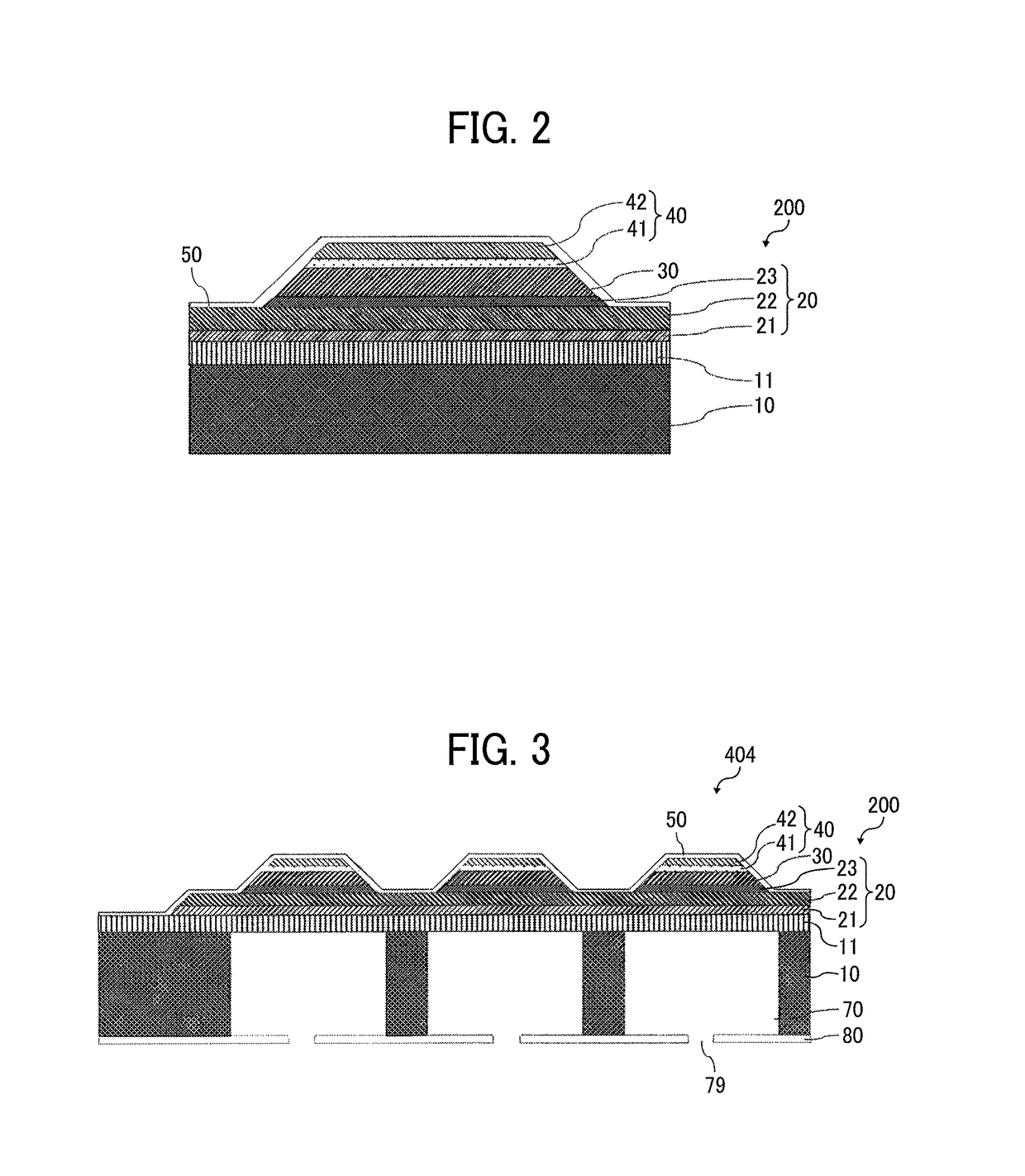
[0145]In the present example, the PZT-film laminated structure 200 illustrated in FIG. 2 was produced. After a thermal oxide film was formed on a surface of the substrate 10 of Si, the lamination-type diaphragm plate 11 is formed by CVD. Specifically, a thermal oxide film (having a film thickness of 600 nm) was formed on a silicon wafer, and a film produced by the LPCVD method was formed on the thermal oxide film. First, a polysilicon film of 200 nm was formed. Then, a silicon oxide film was formed at a thickness of 100 nm. Next, a silicon nitride film was formed at a thickness of 150 nm. Further, a silicon oxide film was formed at a thickness of 150 nm and a silicon nitride film was formed at a thickness of 150 nm. Further, a silicon oxide film was formed at a thickness of 100 nm and a polysilicon film was formed at a thickness of 200 nm. Finally, a silicon oxide film was formed at a thickness of 600 nm. All of the laminated films formed the diaphragm plate 11. Note that, in ...

example 2

[0177]The same procedure as the procedure in Example 1 was performed using a sol-gel liquid in which the amounts of impurities have changed without changing the composition amounts of main ingredients of Ti, Zr, and Pb of the sol-gel liquid. When SIMS analysis was performed on a film obtained similarly with the film of Example 1, Cl / Ti was 0.0113. Using the film, a liquid discharge head was produced in the same manner as the manner of Example 1. When the measurement was performed on the film in the same manner as the measurement of Example 1, the amount of displacement was 0.220 μm.

example 3

[0178]The same procedure as the procedure in Example 1 was performed using a sol-gel liquid in which the amounts of impurities have changed without changing the composition amounts of main ingredients of Ti, Zr, and Pb of the sol-gel liquid. When the SIMS analysis was performed on a film obtained similarly with the film of Example 1, Cl / Ti was 0.030. Using the film, a liquid discharge head was produced in the same manner as the manner of Example 1. Thus, when three liquid discharge heads were produced under the same conditions, the amount of displacement was in a range of 0.213 to 0.223 m. The average value of the amount of displacement was 0.218 μm, and the range of variations was 0.05 rm.


PUM


Abstract

A PZT-film laminated structure includes a substrate, a lower electrode on the substrate, an orientation control layer on the lower electrode, a PZT layer on the orientation control layer, and an upper electrode on the PZT layer. The PZT layer has a (100) or (001) main orientation in which a peak intensity of PZT (100) or (001) is 90% or greater relative to a peak intensity of all PZT peaks in an X-ray diffraction measurement. A ratio of a total value of a secondary ion intensity of Cl relative to a total value of a secondary ion intensity of Ti in the PZT layer is equal to or smaller than 0.03 when the secondary ion intensity of Cl and the secondary ion intensity of Ti in the PZT layer are measured in a direction of thickness of the PZT layer with a magnetic-field secondary ion mass spectrometry.

Description

CROSS-REFERENCE TO RELATED APPLICATION[0001]This patent application is based on and claims priority pursuant to 35 U.S.C. § 119(a) to Japanese Patent Application No. 2016-001789 filed on Jan. 7, 2016 in the Japan Patent Office, the entire disclosure of which is hereby incorporated by reference herein.BACKGROUND[0002]Technical Field[0003]Aspects of the present disclosure relate to a PZT-film laminated structure, a liquid discharge head, a liquid discharge device, a liquid discharge apparatus, and a method of making the PZT-film laminated structure.[0004]Related Art[0005]Recent years, piezoelectric actuators have been increasingly used. As piezoelectric ceramics used as actuator, for example, composite oxides are known that have perovskite crystal structures and can be represented by a chemical formula, ABO3. Among the composite oxides, as a material most generally used for many years, for example, lead zirconate titanate (PZT) is widely known in which lead (Pb) is applied to A and a ...

Claims


Application Information

Patent Timeline
Patent Type & Authority Patents(United States)
IPC IPC(8): B41J2/14
CPCB41J2/14233B41J2202/03B41J2002/14241
Inventor SHINKAI, MASARUAKIYAMA, YOSHIKAZUMIZUKAMI, SATOSHI
Owner RICOH KK
Why Eureka
Try Eureka