Three-dimensional imaging radar system and method based on a plurality of times of integral

a three-dimensional imaging and integral technology, applied in the field of three-dimensional imaging radar system, can solve the problems of low imaging speed, poor imaging resolution, limited imaging resolution, etc., and achieve the effects of reducing data processing difficulty, reducing interference, and increasing accuracy

Active Publication Date: 2018-05-01
ZHEJIANG GENIUSPROS TECH CO LTD
View PDF6 Cites 4 Cited by
  • Summary
  • Abstract
  • Description
  • Claims
  • Application Information

AI Technical Summary

Benefits of technology

[0020]The invention has the following beneficial effects. The working procedure of the light sensing elements of the image sensor is a light intensity integral procedure, the integral image in different time domains can be obtained as the light is sensed by the image sensor in different time, the distance and depth information of the target can be obtained by comparing the two integral images, and the position of the reflected object in the scope can be obtained by the continuous three times of exposure, thus to reduce the difficulty of data processing and to obtain the three-dimensional image with the greater anti-interference and higher accuracy. As the prior three-dimensional laser radar acquires the nanosecond light source and detector, in this invention, the three-dimensional imaging radar may be realized by the common LED light source and common CCD or CMOS planar array, thereby greatly reducing the system cost, and realizing the high-speed and high-resolution three-dimensional imaging, further to develop new application of the three-dimensional imaging radar in the vehicle anti-collision field, such as automobiles or helicopters, and the three-dimensional topography mapping field.

Problems solved by technology

However, to realize the three-dimensional imaging with a high resolution, points need to be scanned one by one, which is the most commonly used laser imaging radar at present, with a very low imaging speed and a very bad imaging resolution.
The measurement accuracy of this way is limited to the shape of the light pulse, the imaging resolution is limited to the image intensifier, and the manufacturing cost is high, which may be only used for military and national defense.
Since the phase is limited to 2π, the measuring distance of this measurement is limited to several meters, and the measuring accuracy is not high.
For example, although the element requirement of the scanned laser radar is lower and the work distance is further, the requirement for the scanning mechanism is higher, the frame rate is lower, and the real-time performance is worse; although the real-time performance of the planar array laser radar is great, the great planar array element is needed for high-resolution imaging, and the cost and research difficulty of the element is high.
The cost of this measurement is lower than other planar array technique.
However, since expensive elements such as lasers are used, the total cost is still higher, and the detecting distance and accuracy is greatly limited.

Method used


Image

  • Three-dimensional imaging radar system and method based on a plurality of times of integral
  • Three-dimensional imaging radar system and method based on a plurality of times of integral
  • Three-dimensional imaging radar system and method based on a plurality of times of integral

Examples


Embodiment Construction

[0024]The invention is described according to the figures, and the objective and effect of the invention may be better understood.

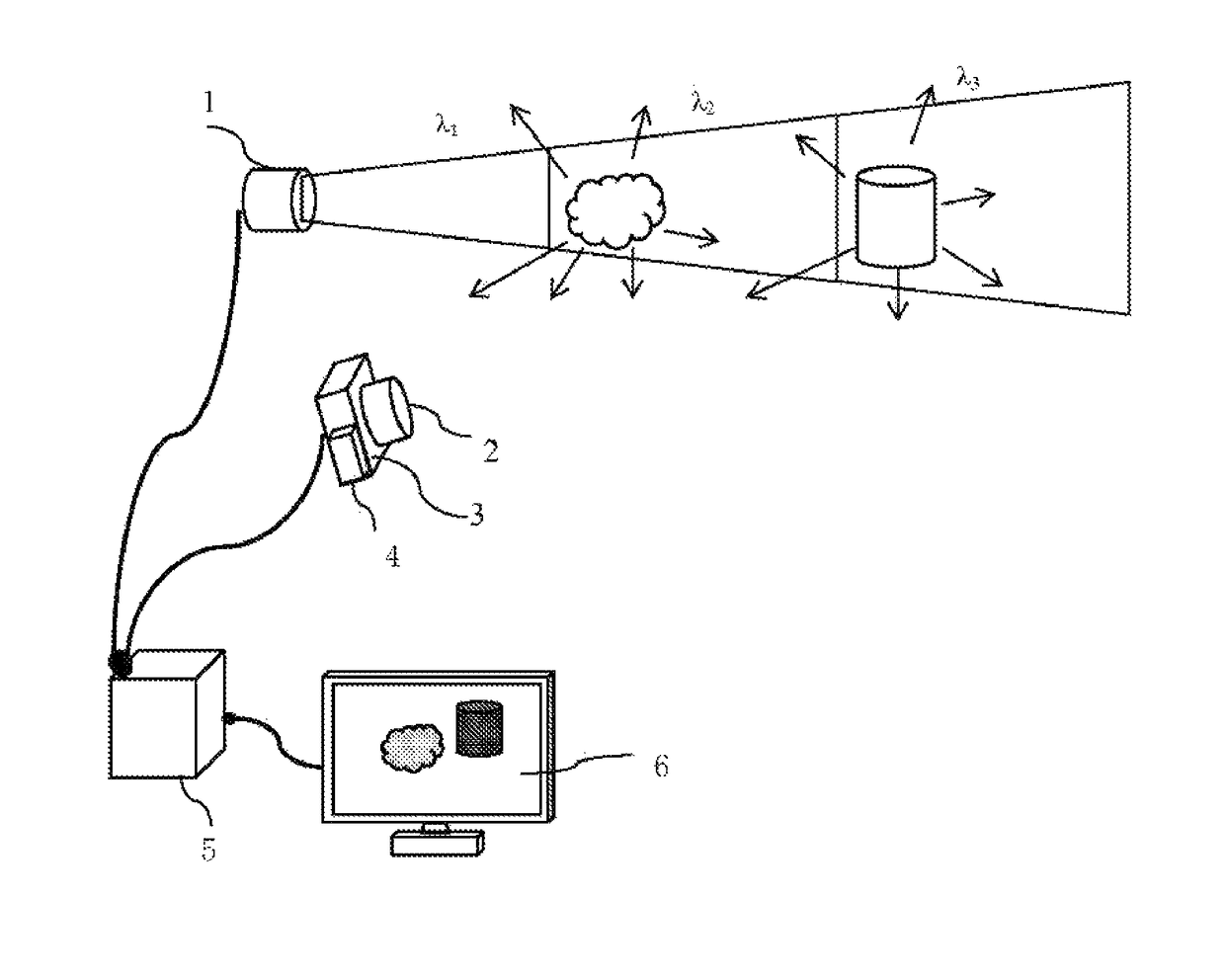
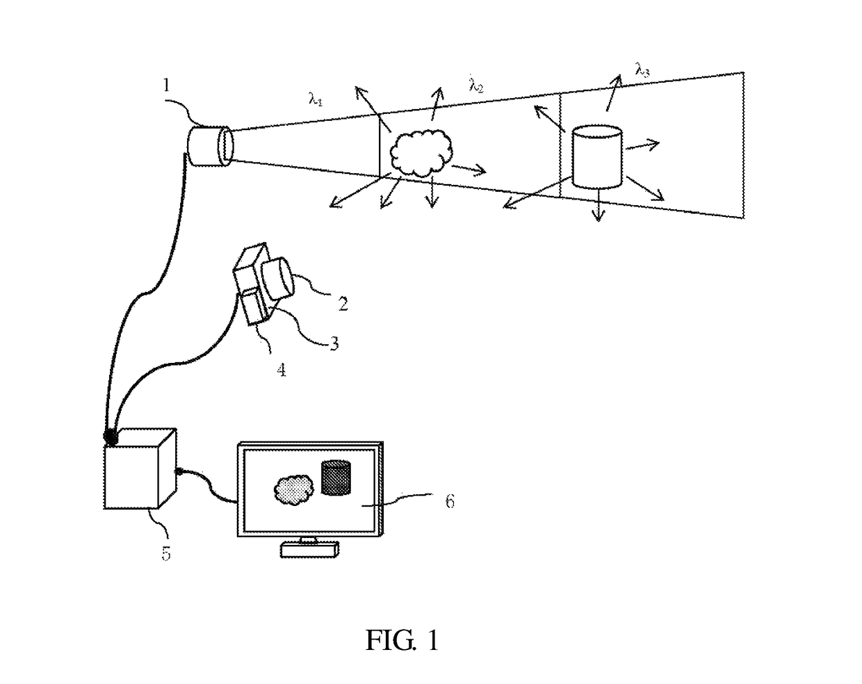
[0025]In FIG. 1, the three-dimensional imaging radar system based on a plurality of times of integral in the invention, includes an LED light source 1, an optical band-pass filter 2, an image sensor 3, an electronic shutter 4, a data processor 5, and a display terminal 6; the optical band-pass filter 2 and the electronic shutter 4 are fixed to the image sensor 3, the LED light source 1 and the image sensor 3 are connected with the data processor 5, the data processor 5 is connected with the display terminal 6; the LED light source 1 generates a series of light pulse trains, when these light pulse trains illuminate an object, the object reflects the light in succession; the reflected light is sensed by the image sensor 3 through the optical band-pass filter 2, to form an image on the image sensor 3; the image sensor performs exposure imaging three times in...


PUM


Abstract

This invention discloses a three-dimensional imaging radar system and method based on a plurality of times of integral. The system includes an LED light source, an optical band-pass filter, an image sensor, an electronic shutter, a data processor, and a display terminal. The LED light source generates a series of light pulse trains, and when the light pulse trains illuminate an object, the object reflects the light in succession. The reflected light is sensed by the image sensor through the optical band-pass filter, to form an image on the image sensor. The image sensor performs exposure imaging three times in succession for the reflected light of the same pulse under the action of the electronic shutter. The data processor analyzes the three images to obtain contour information and distance information about the object. Finally, the display terminal displays results.

Description

BACKGROUND OF THE INVENTION[0001]Field of the Invention[0002]The invention relates to an imaging radar system and, more particularly, to a three-dimensional imaging radar system and method based on flight spectrum.[0003]Description of the Related Art[0004]Three-dimensional imaging radar technique can be widely applied to different fields, such as an anti-collision system of vehicles, a photographing measurement system on freeway, a range-measuring telescope, and machine vision. A three-dimensional imaging radar is an imaging system capable of measuring ranges, and the system includes an emitting part, a receiving part, and an information processing part. At present, the range-measuring principle of the radar includes fight time measurement, phase difference measurement, and triangulation.[0005]The first measurement is the fight time measurement. In this measurement, a pulse light source is used, and a distance to a target object is calculated by measuring the time difference between...

Claims


Application Information

Patent Timeline
Patent Type & Authority Patents(United States)
IPC IPC(8): G01C3/08G01S17/89G01S17/10G01S7/486G01S7/4865G01S7/4861G01S17/18G01S17/894
CPCG01S17/89G01S17/107G01S7/4865G01S7/4861G01S17/18G01S17/894
Inventor FU, JIANZHANG, XIUDALV, JUNGU, YINGJIE
Owner ZHEJIANG GENIUSPROS TECH CO LTD
Why Eureka
Try Eureka