
Methods and apparatus for enabling proximity services in mobile networks

a technology of mobile networks and proximity services, applied in the field of wireless communication systems, can solve the problems of weak interference towards, serious degradation of the performance of both cellular and device to device networks, and increase the level of interference, so as to effectively reduce the second level interference to the network, the effect of enhancing the efficiency of proximity services

Active Publication Date: 2018-05-01
MIAO GUOWANG
View PDF24 Cites 18 Cited by
  • Summary
  • Abstract
  • Description
  • Claims
  • Application Information

AI Technical Summary

Benefits of technology

The patent introduces a way to make devices in proximity more efficient by allowing them to locate each other without needing a central location system. This reduces interference to the network and allows for lower power communication between devices. This technology can be applied to any type of device-to-device communication, such as Wi-Fi-direct or cellular networks.

Problems solved by technology

When downlink resources are reused, device to device links may cause strong interference towards existing cellular user equipment, whereas in the case of sharing uplink resources, the interference caused by device to device links will affect only the base stations, where the impact has been determined to be less harmful.
As more device to device pairs exist in the network, the interference levels may increase to a point where the performance of both cellular and Device to Device networks could be seriously degraded.
Thus, one of the main limitations on the scalability of Device to Device communications is interference control.
The first level of interference includes inter-cell interference.
However, the resources are shared by several cells causing inter-cell interference between the Cellular User Equipment and base stations of different cells.

Method used


Image

  • Methods and apparatus for enabling proximity services in mobile networks
  • Methods and apparatus for enabling proximity services in mobile networks
  • Methods and apparatus for enabling proximity services in mobile networks

Examples


an implementation example

[0288]A detailed implementation example of the invented interference coordination technollogies.

[0289]Define φxk ∈{0, 1}, ∀x ∈{1, . . . , N}∀k ∈{1, . . . , N^x}, as a binary random variable that indicates the state of a Device to Device link. For φxk=1 the Device to Device link k in cell x is active, i.e. in the device to device mode, otherwise φxk=0. The parameter N corresponds to the number of cells in the system and N^x is the number of available device to device links in cell x.

[0290]The maximum level of interference that can be tolerated in the system is given by the Signal-to-Interference-plus-Noise Ratio requirements for the Cellular User Equipment and device to device links, depicted in (2.1a) and (2.1b), respectively. An upper bound for the transmission power of device to device links shown in (2.1c).

[0291]Γx⁢⁢0=Px⁢⁢0⁢Gx⁢⁢0⁢x⁢⁢0Ix⁢⁢0D⁢⁢2⁢⁢D+Ix⁢⁢0CUE+𝒩BS≥γx⁢⁢0th,(2.1⁢a)Γx⁢⁢k=ϕx⁢⁢k⁢Px⁢⁢k⁢Gx⁢⁢k⁢⁢x⁢⁢kIx⁢⁢kD⁢⁢2⁢⁢D+Ix⁢⁢kCUE+𝒩D≥γx⁢⁢kth,(2.1⁢b)ϕxk⁢Pxk≤PDma⁢⁢x,⁢∀x∈{1,…⁢,N}⁢⁢∀k∈{1,...


PUM


Abstract

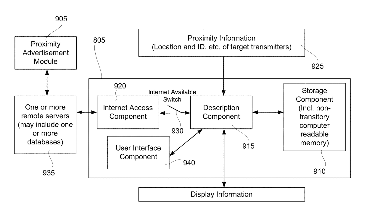
Apparatus, system or method to improve communications in a wireless communication network. Steps may include sending specific information to user equipment or adjacent base stations so that the user equipment and adjacent base stations can determine interference levels in sidelink communications. The apparatus may include a location-estimation component interconnected with a self-tracking component and a signal-detection component. The apparatus may include a proximity system implemented using instructions stored in a non-transitory computer readable medium and the proximity system may be usable to locate one or more target transmitters. In some embodiments, the system may include other modules such as a localization module; a proximity-description module; and a proximity-display module. The proximity system may also include a proximity advertisement module, which includes an access management component; an ownership management component; and a content management component.

Description

CROSS-REFERENCE TO RELATED APPLICATIONS[0001]This application is a continuation in part of U.S. patent application Ser. No. 15 / 112,173, filed 16 Jul. 2016; application Ser. No. 15 / 112,173 was a continuation of, and a national stage entry of, PCT / US2015 / 058819 filed 3 Nov. 2015 with article 19 amendments filed Mar. 14, 2016; PCT / US2015 / 058819 claimed the priority benefit of U.S. Provisional Application No. 62 / 085,327, filed 27 Nov. 2014, and U.S. Provisional Application No. 62 / 235,697, filed 1 Oct. 2015; the entire contents of all of these applications are hereby incorporated herein by reference.TECHNICAL FIELD[0002]In the field of wireless communication systems, methods and devices are disclosed that enable individual mobile devices to determine if a device to device link within a cell may be created and how these devices should communicate.BACKGROUND[0003]This Background section of this specification is intended to provide a background or context to the invention that is recited in...

Claims


Application Information

Patent Timeline
Patent Type & Authority Patents(United States)
IPC IPC(8): H04W24/00H04W4/02H04W4/00H04W88/02H04W88/08
CPCH04W4/70H04W4/02H04W4/005H04W88/02H04W88/08H04W4/023H04W4/029Y02D30/70
Inventor MIAO, GUOWANG
Owner MIAO GUOWANG
Learn More