Method and apparatus for clearance control utilizing fuel heating

a technology of fuel heating and clearance control, which is applied in the direction of turbine/propulsion fuel heating, mechanical equipment, machines/engines, etc., can solve the problems of reducing the capacity of the coolant to heat and the clearance at fsfl that would otherwise occur, so as to reduce the capacity, reduce the clearance at fsfl, and reduce the capacity

Active Publication Date: 2018-05-08
GENERAL ELECTRIC CO
View PDF50 Cites 1 Cited by
  • Summary
  • Abstract
  • Description
  • Claims
  • Application Information

AI Technical Summary

Benefits of technology

[0010]The flow rate of fuel increases to transition the gas turbine from full speed, no load (FSNL) to full speed, full load (FSFL). As the fuel flow rate increases, there is a similar increase in the cooling, e.g., reduced temperature, of the coolant. The increased cooling reduces the capacity of the coolant to heat and thermally expand the turbine casing during FSFL operation. The reduced capacity results in a reduction in the clearance at FSFL that would otherwise occur if the coolant was not cooled by the fuel.
[0011]While the fuel flow is relatively low, the coolant is cooled to a much lesser extend than when the fuel flow is high. During low fuel flow, the coolant remains relatively hot and thus causes the turbine casing to thermally expand to a greater extent than if the coolant had been cooled by a greater fuel flow. Allowing the turbine casing to thermally expand during low fuel flow may be used to increase the clearance while the fuel flow is low such as during FSNL.
[0012]By using fuel flow to cool the coolant flowing to the turbine casing, a passive clearance control system may be configured that allows for increased clearance during low fuel flow operations and reduced clearance during high fuel flow operations. This ability may be useful for gas turbines having clearance pinch points during low fuel flow operations.

Problems solved by technology

The increased cooling reduces the capacity of the coolant to heat and thermally expand the turbine casing during FSFL operation.
The reduced capacity results in a reduction in the clearance at FSFL that would otherwise occur if the coolant was not cooled by the fuel.

Method used


Image

  • Method and apparatus for clearance control utilizing fuel heating
  • Method and apparatus for clearance control utilizing fuel heating
  • Method and apparatus for clearance control utilizing fuel heating

Examples


Embodiment Construction

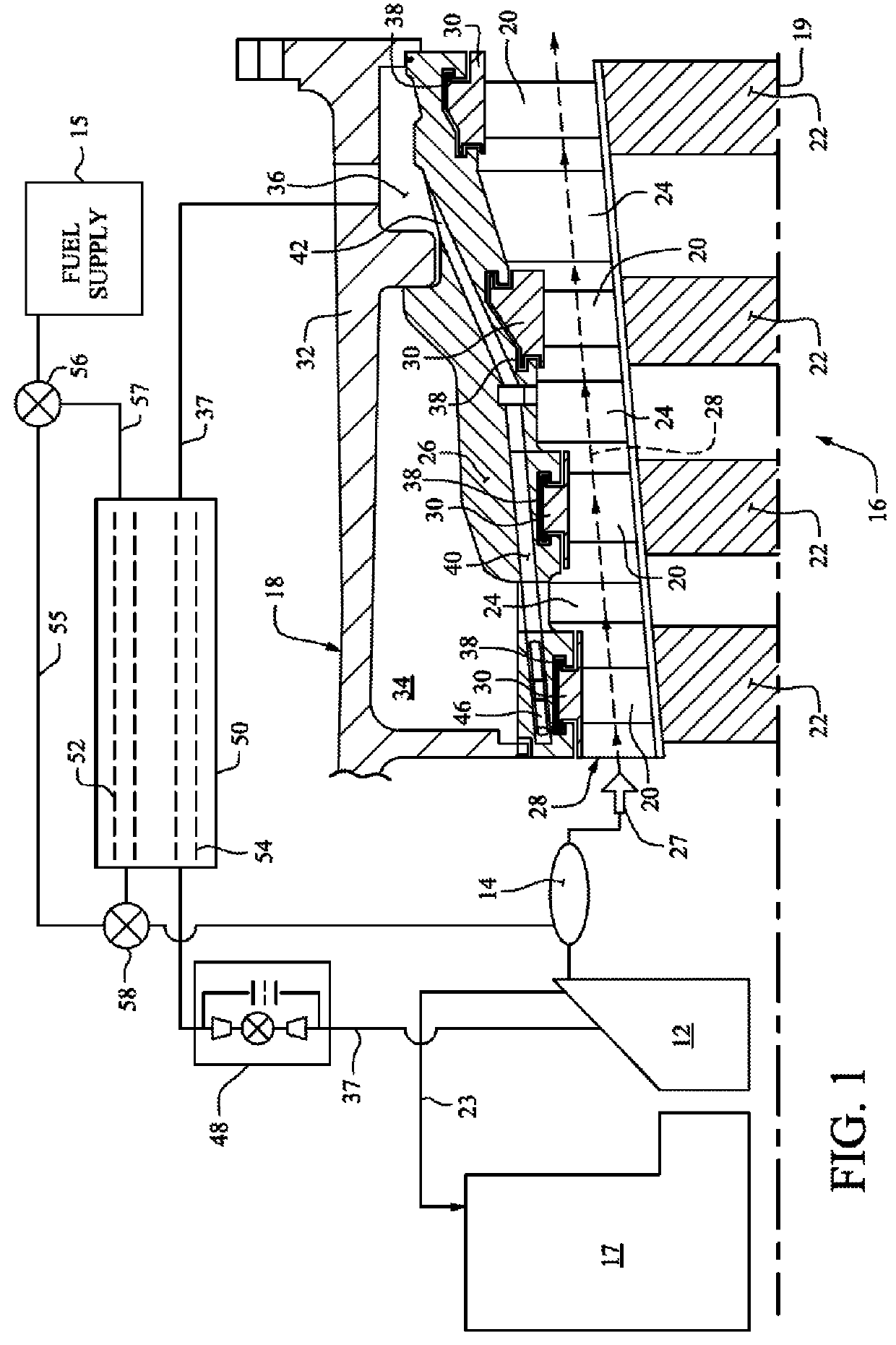
[0020]FIG. 1 shows a gas turbine 10 having a compressor 12, combustor 14 and turbine 16. An inlet duct 17 provides a passage for air to enter the gas turbine and be directed to the inlet to the compressor.

[0021]Gas turbines generate power by compressing air, mixing the compressed air with fuel 15, combusting the mixture and driving a turbine with combustion gases. The turbine includes an annular casing 18 that houses rows of turbine buckets 20 (also referred to as blades) that rotate about a shaft 19. The buckets in each row are mounted on a turbine wheel 22. Between the rows of buckets are rows of stationary nozzles 24 (also referred to as guide vanes. Hot combustion gases 27 (see arrow) flow in an annular hot gas passage 28 through the rows of buckets 20 and nozzles 24. The turbine casing 18 forms the outer surface of the hot gas passage 28. The inner wall of the passage 28 is near the outer rims of the wheels 22.

[0022]A conduit 23 for compressed air extracted from the compressor ...


PUM


Abstract

A clearance control apparatus providing compressed cooling air to a turbine casing in a gas turbine, the apparatus including: a cooling gas passage extending through an inner annular shell of the turbine casing; a cooling gas conduit connected to a compressor of the gas turbine and to the turbine casing, wherein the cooling gas conduit receives compressed air from the compressor and delivers the compressed air to the turbine casing, and wherein the cooling gas conduit is in fluid communication with the cooling gas passage, and a heat exchanger connected to the cooling gas conduit and to a fuel conduit delivering fuel to a combustor of the gas turbine, wherein the heat exchanger transfers heat from the cooling gas to the fuel.

Description

BACKGROUND OF THE INVENTION[0001]The present invention relates to clearance control in a turbine, such as a gas turbine.[0002]Clearance in a turbine typically refers to the dimension of gaps between the rotor and the stator casing that surrounds the rotor. The rotor is typically an axial turbine having rows of buckets each mounted on a turbine wheel. The wheels are mounted on a shaft of the turbine. The stator casing houses the rotor and includes rows of stationary nozzles positioned between the rows of buckets. Clearance often refers to the annular gap between the tips of the buckets and the stator casing.[0003]Clearance is needed to allow the buckets to rotate without rubbing against the stator casing. If the clearance is too great, combustion gases may leak over the tips of the buckets and do not drive the rotation of the turbine. If the clearance is too small, the tips may rub against the stator casing and may cause vibrations that damage the turbine.[0004]The clearance varies a...

Claims


Application Information

Patent Timeline
Patent Type & Authority Patents(United States)
IPC IPC(8): F01D11/24F02C6/08F02C7/224F02C7/18
CPCF01D11/24F02C7/185F02C7/224F05D2260/221F02C6/08F05D2260/213
Inventor BALLARD, JR., HENRY G.BEADIE, DOUGLAS FRANKMEMMER, JOHN DAVID
Owner GENERAL ELECTRIC CO
Why Eureka
Try Eureka