Superelastic fluid conduit for a gas turbine engine

a gas turbine engine and fluid conduit technology, applied in the direction of machines/engines, efficient propulsion technologies, light and heating apparatus, etc., can solve the problems of large damping, achieve maximum damping, reduce vibration, and minimise the resonance of the conduit

Active Publication Date: 2018-05-15
ROLLS ROYCE PLC
View PDF11 Cites 1 Cited by
  • Summary
  • Abstract
  • Description
  • Claims
  • Application Information

AI Technical Summary

Benefits of technology

[0010]Advantageously, it has been found that superelastic materials provide the necessary strength, rigidity and resistance to vibration at the necessary temperatures to provide a fluid conduit which substantially removes the need for pigtails, thus resulting in a lightweight conduit, with a long service life. Simultaneously, by installing the conduit such that it is subject to stress such that the material is in a superelastic or a plastic region of the material, the conduit is damped, reducing the need for bends in the material.
[0031]The damping requirements may be met by pre-loading the conduit or conduit sections such that, in use, the sum of the pre-load and a load applied in use match a hysteresis band of the superelastic material. Advantageously, the conduit provides maximum damping for the or each section of the conduit, thereby further reducing vibrations, which may lead to reduced noise and / or increased longevity of the conduit.

Problems solved by technology

These alloys also have large hysteresis effects when stressed and released, thereby leading to large amounts of damping.

Method used


Image

  • Superelastic fluid conduit for a gas turbine engine
  • Superelastic fluid conduit for a gas turbine engine
  • Superelastic fluid conduit for a gas turbine engine

Examples


Embodiment Construction

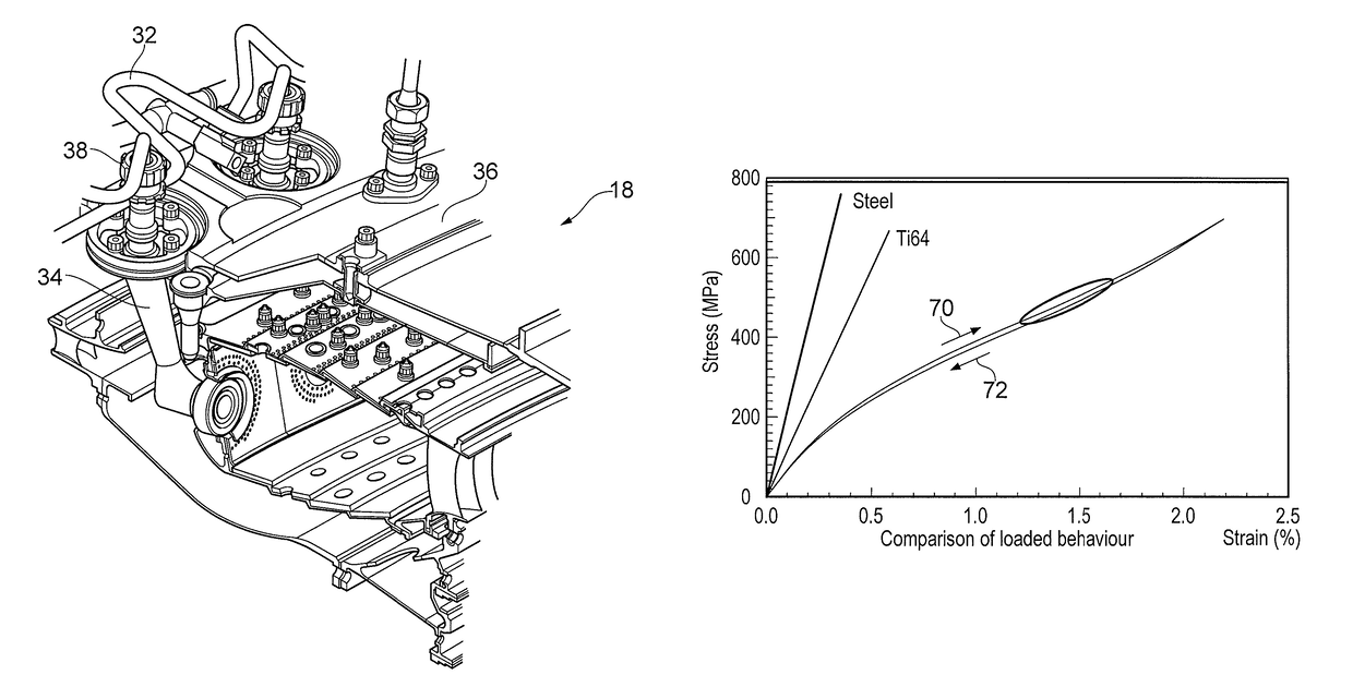
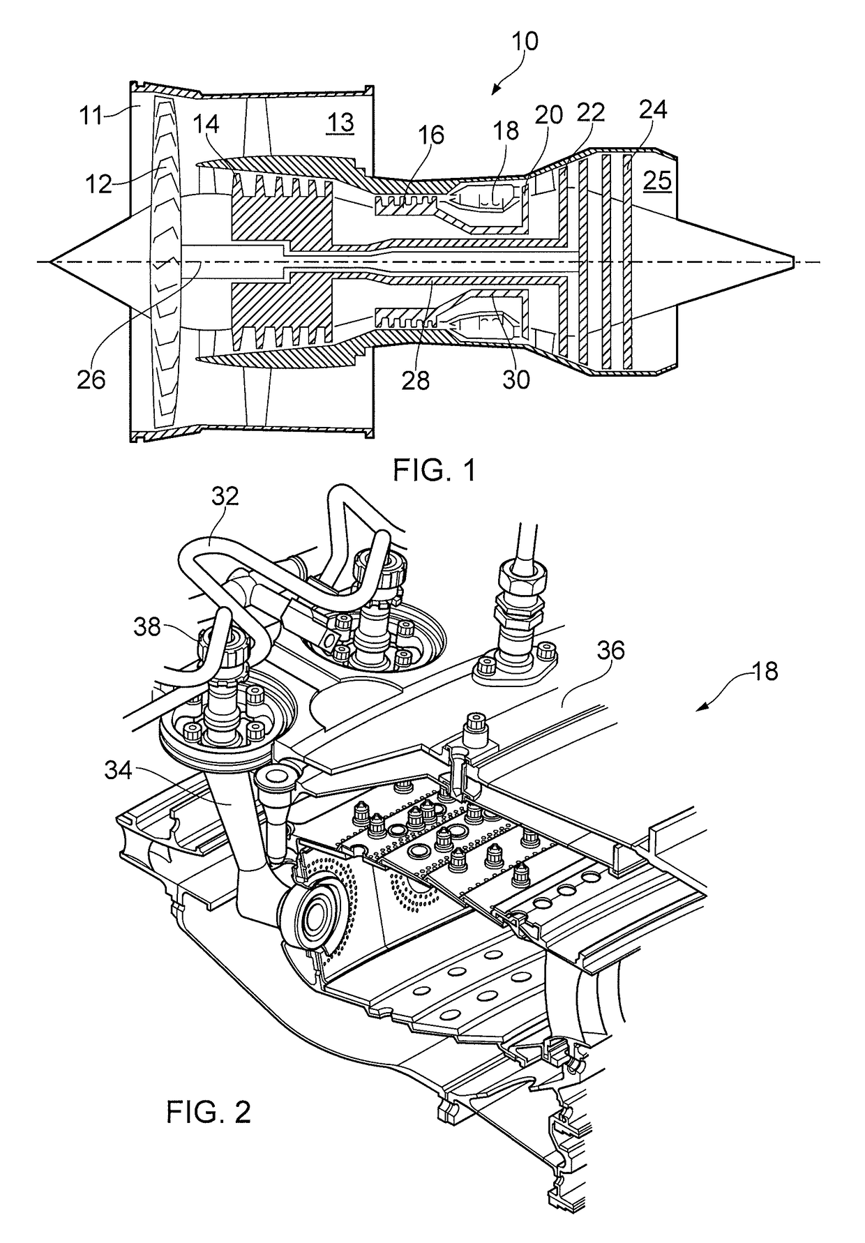
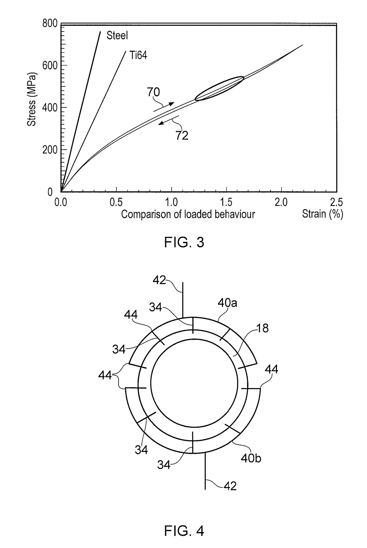
[0038]FIG. 1 shows a high-bypass gas turbine engine 10. The engine 10 comprises, in axial flow series, an air intake duct 11, an intake fan 12, a bypass duct 13, an intermediate pressure compressor 14, a high pressure compressor 16, a combustor 18, a high pressure turbine 20, an intermediate pressure turbine 22, a low pressure turbine 24 and an exhaust nozzle 25. The fan 12, compressors 14, 16 and turbines 20, 22, 24 all rotate about the major axis of the gas turbine engine 10 and so define the axial direction of gas turbine engine.

[0039]Air is drawn through the air intake duct 11 by the intake fan 12 where it is accelerated. A significant portion of the airflow is discharged through the bypass duct 13 generating a corresponding portion of the engine 10 thrust. The remainder is drawn through the intermediate pressure compressor 14 into what is termed the core of the engine 10 where the air is compressed. A further stage of compression takes place in the high pressure compressor 16 b...


PUM

PropertyMeasurementUnit
temperaturesaaaaaaaaaa
Shear modulusaaaaaaaaaa

Abstract

A fluid conduit for a gas turbine engine. The conduit includes a superelastic material such as TNTZ or Ti2448. The conduit is installed such that at least part of the conduit is subject to a stress which lies in one of a superelastic and a plastic region of the material in use.

Description

FIELD OF THE INVENTION[0001]The present invention relates to a fluid conduit for a gas turbine engine, a gas turbine engine incorporating a fluid conduit, and to a method of designing a fluid conduit for a gas turbine engine.BACKGROUND TO THE INVENTION[0002]FIG. 1 shows a high-bypass gas turbine engine in the form of a turbofan 10. The engine 10 comprises, in axial flow series, an air intake duct 11, an intake fan 12, a bypass duct 13, an intermediate pressure compressor 14, a high pressure compressor 16, a combustor 18, a high pressure turbine 20, an intermediate pressure turbine 22, a low pressure turbine 24 and an exhaust nozzle 25. The fan 12, compressors 14, 16 and turbines 20, 22, 24 all rotate about the major axis of the gas turbine engine 10 and so define the axial direction of gas turbine engine. Alternatively, the shaft power could be used to drive other mechanical loads, such as a marine propeller or an electrical generator.[0003]Air is drawn through the air intake duct 1...

Claims


Application Information

Patent Timeline
Patent Type & Authority Patents(United States)
IPC IPC(8): F02C7/22F01D25/04F16L9/02
CPCF02C7/222F01D25/04F05D2240/35F05D2260/96Y02T50/671F05D2300/174F05D2300/175F05D2300/501F16L9/02F05D2260/98Y02T50/60F23R3/28
Inventor FLETCHER, PAULWEBSTER, JOHN RICHARDMORAN, ANTHONY JOHN
Owner ROLLS ROYCE PLC
Why Eureka
Try Eureka