Method of diagnosing an exhaust gas sensor

a technology of exhaust gas sensor and diagnostic method, which is applied in the direction of electric control, machines/engines, instruments, etc., can solve the problems of increasing emissions and/or reducing vehicle drivability, and achieve the effects of reducing vehicle drivability, enhancing engine operation, and increasing emissions

Active Publication Date: 2018-05-15
FORD GLOBAL TECH LLC
View PDF4 Cites 4 Cited by
  • Summary
  • Abstract
  • Description
  • Claims
  • Application Information

AI Technical Summary

Benefits of technology

[0002]An exhaust gas sensor may be positioned in an exhaust system of a vehicle to detect an air-fuel ratio of exhaust gases exiting an internal combustion engine of the vehicle. Exhaust gas sensor readings may be used to control operation of the internal combustion engine to propel the vehicle. Specifically, fuel injection amounts to the cylinders can be adjusted in response to the detected air-fuel ratio. Degradation of an exhaust gas sensor may result in increased emissions and / or reduced vehicle drivability. Accordingly, accurate determination of sensor degradation particularly prior to delivering the vehicle for road operation may provide enhanced engine operation.
[0005]In this way, a degraded exhaust gas sensor may be detected prior to putting the vehicle into operation on the road. By determining individual concentrations of a plurality of exhaust constituents with a gas analyzer, a more accurate air-fuel ratio can be calculated, allowing a more robust determination of exhaust gas sensor degradation.

Problems solved by technology

Degradation of an exhaust gas sensor may result in increased emissions and / or reduced vehicle drivability.

Method used


Image

  • Method of diagnosing an exhaust gas sensor
  • Method of diagnosing an exhaust gas sensor
  • Method of diagnosing an exhaust gas sensor

Examples


Embodiment Construction

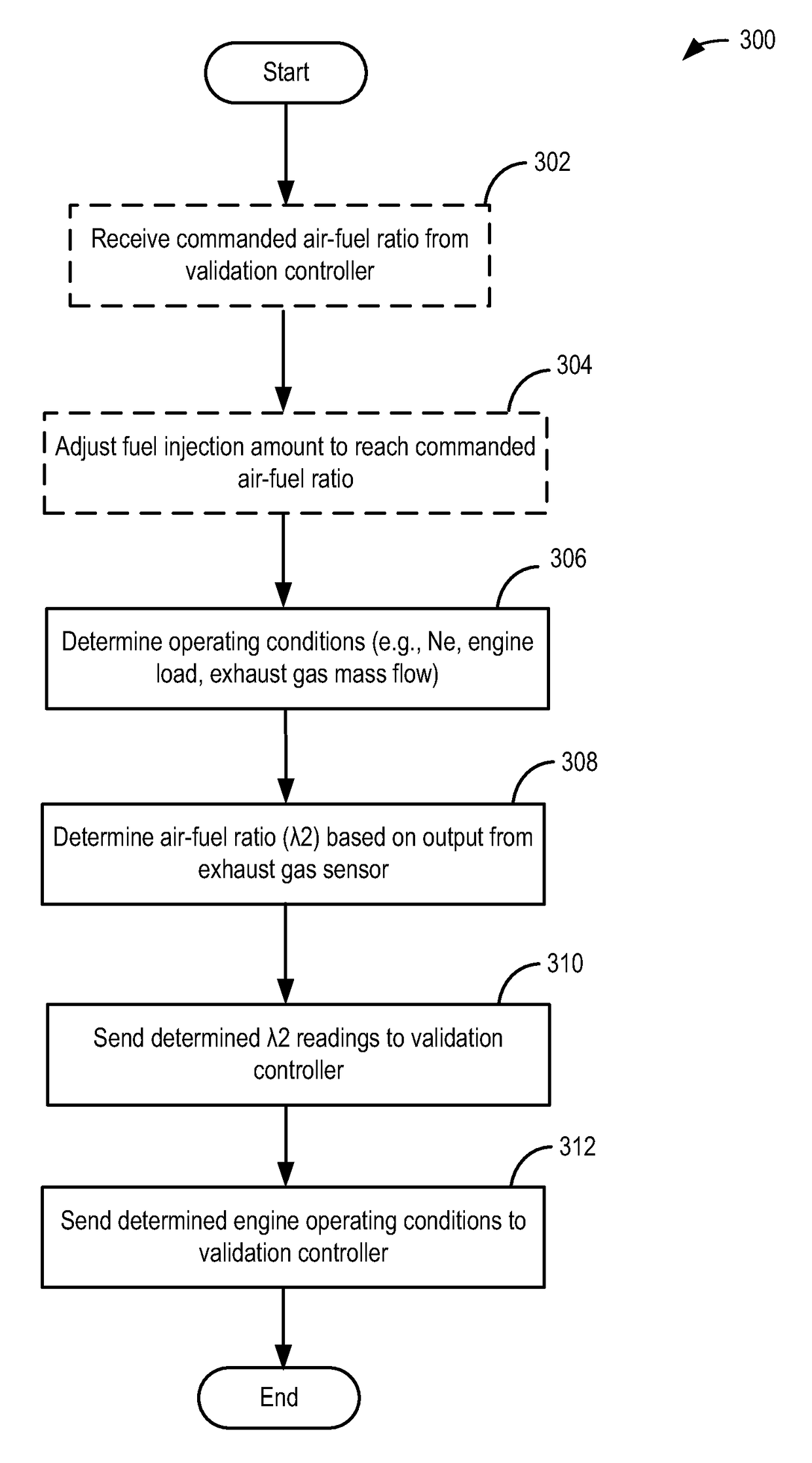
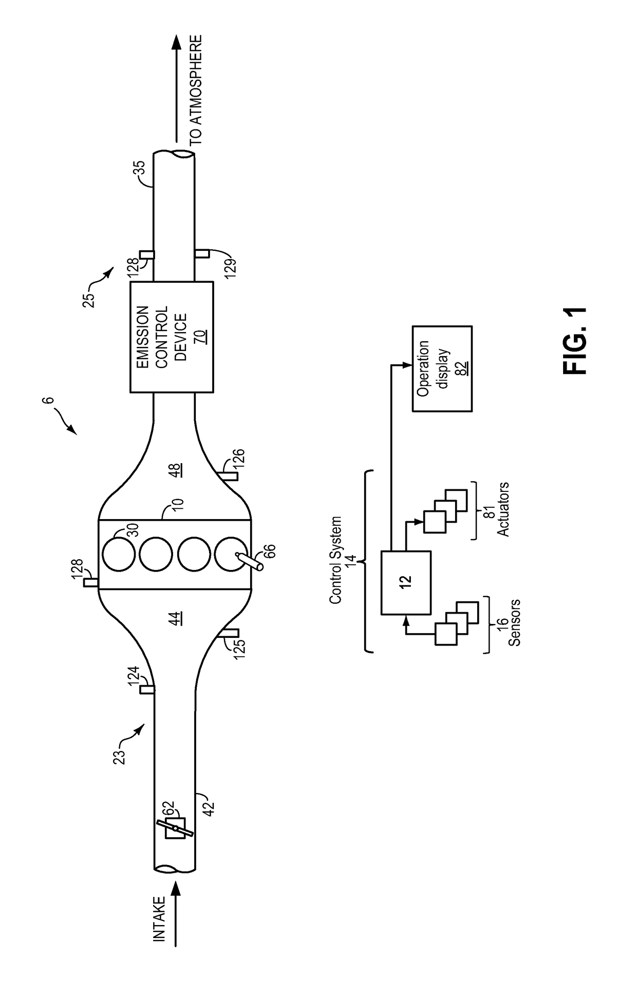
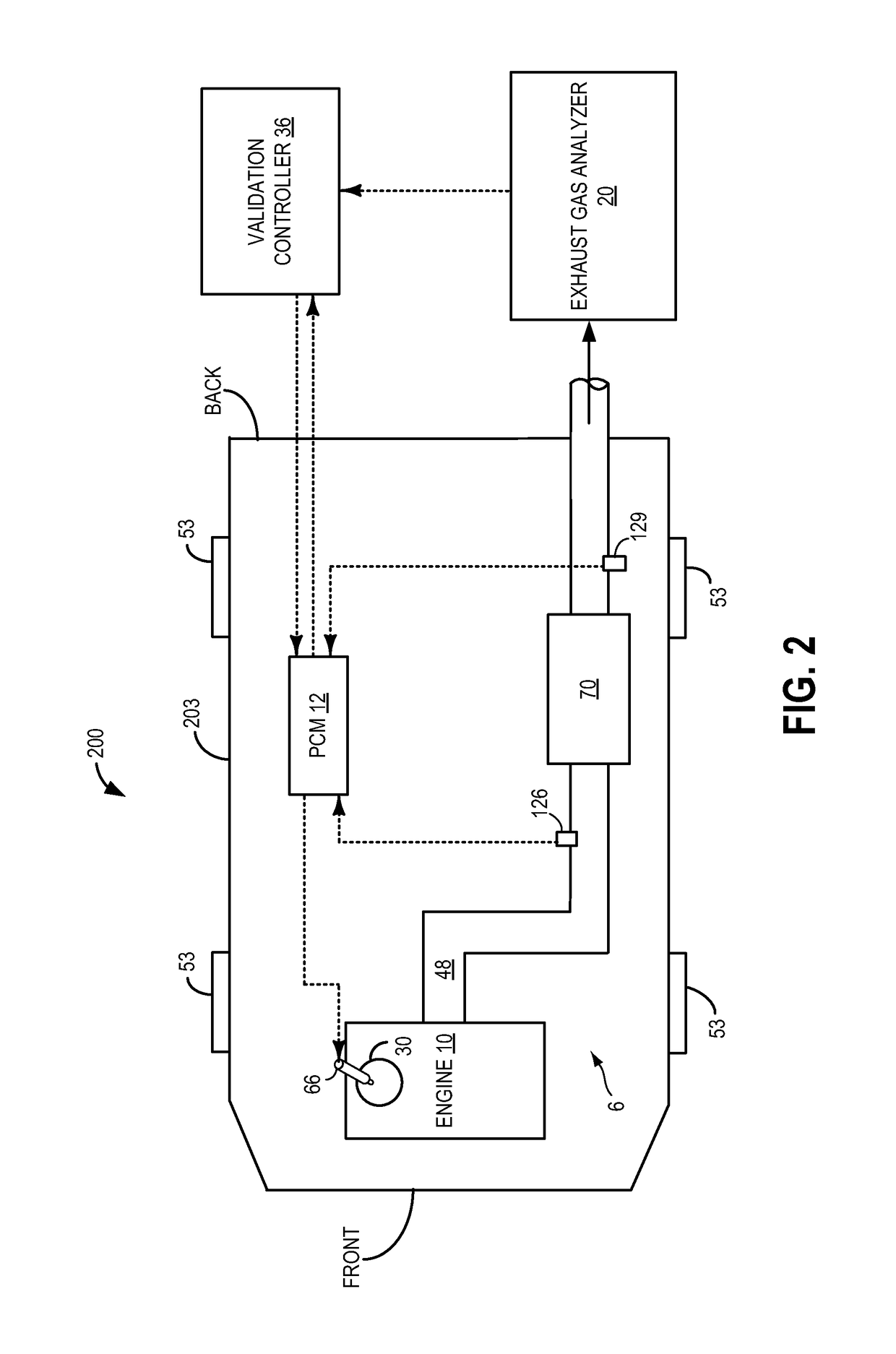
[0012]Exhaust gas sensors may be provided in an exhaust passage of a vehicle, such as that shown in FIGS. 1 and 2, to determine the air-fuel ratio in exhaust gases exiting an engine. Prior to operating the vehicle on-road, exhaust gas sensors may be diagnosed for degradation by evaluating their performance on a test bench. Herein, the engine may be operated at a specific air-fuel ratio and an exhaust air-fuel ratio may be determined from the output of the exhaust gas sensor by the engine controller (FIG. 3). As the engine continues to operate at a specific air-fuel ratio, emissions from the tailpipe may be fed into a gas analyzer that is coupled to a validation controller. Concentrations of emission constituent species, such as oxygen (O2), hydrogen (H2), carbon monoxide (CO), hydrocarbons (HC), nitrogen oxide (NO), and ammonia (NH3) may be measured by the gas analyzer and transferred to the validation controller. A second exhaust air-fuel ratio may be determined by the validation c...


PUM

PropertyMeasurementUnit
thresholdaaaaaaaaaa
thresholdaaaaaaaaaa
concentrationsaaaaaaaaaa

Abstract

Embodiments for an engine exhaust are provided. In one example, a method comprises categorizing each respective concentration of a plurality of exhaust gas constituents measured by a gas analyzer into one of oxidants or reductants, the gas analyzer receiving exhaust gas flow from an engine. The method also includes determining an exhaust air-fuel ratio based on the categorized concentrations and validating output from an exhaust gas sensor receiving exhaust gas flow from the engine based on the determined exhaust air-fuel ratio.

Description

FIELD[0001]The present application relates to methods for detecting exhaust gas sensor degradation.BACKGROUND AND SUMMARY[0002]An exhaust gas sensor may be positioned in an exhaust system of a vehicle to detect an air-fuel ratio of exhaust gases exiting an internal combustion engine of the vehicle. Exhaust gas sensor readings may be used to control operation of the internal combustion engine to propel the vehicle. Specifically, fuel injection amounts to the cylinders can be adjusted in response to the detected air-fuel ratio. Degradation of an exhaust gas sensor may result in increased emissions and / or reduced vehicle drivability. Accordingly, accurate determination of sensor degradation particularly prior to delivering the vehicle for road operation may provide enhanced engine operation.[0003]The inventors herein have recognized the above issues and identified approaches to at least partly address the issues. In one example, a method comprises categorizing each respective concentra...

Claims


Application Information

Patent Timeline
Patent Type & Authority Patents(United States)
IPC IPC(8): F02D41/00F02D41/14G01N33/00
CPCG01N33/007F02D41/1495
Inventor KUMAR, PANKAJMAKKI, IMAD HASSAN
Owner FORD GLOBAL TECH LLC
Why Eureka
Try Eureka