LED unit module, light-emitting device, and light source system

a technology of light-emitting devices and unit modules, applied in semiconductor devices for light sources, lighting and heating apparatus, planar light sources, etc., can solve the problems of low life of metal halide discharge lamps, low color saturation of color lights generated by filter plates, and inability to give bright colors. to achieve the effect of improving the uniformity of ligh

Active Publication Date: 2018-05-15
YLX INC
View PDF40 Cites 9 Cited by
  • Summary
  • Abstract
  • Description
  • Claims
  • Application Information

AI Technical Summary

Benefits of technology

[0008]Accordingly, the present invention is directed to an LED unit module that prevents the problem of increased etendue and can achieve uniform light mixing.
[0027]Compared to conventional technologies, embodiments of the present invention have the following advantages:
[0028]Because the LED chipset including at least five LED chips and four colors are disposed on the same substrate, the downstream optics can provide one collimating unit for each LED chipset; because the light from LEDs has a Lambertian distribution, the multiple color lights from one LED chipset is collimated by the collimating unit into a parallel light beam and at the same time mixed into a uniform light beam. The different color lights in the parallel light beam spatially overlap with each other, and have similar corresponding angular distributions; this improves the uniformity of the light generated by the light source. Moreover, the light emitting surface of LED chipset in the LED unit module has an outline shape close to an equal-sided hexagon, which matches the equal-sided hexagon shape of the lens units of the second fly-eye lens of the fly-eye lens pair in the downstream optical path. This prevents etendue increase of the light outputted by the second fly-eye lens.

Problems solved by technology

This type of light sources have the disadvantage that the life of metal halide discharge lamps is low, typically from a few hundred to a few thousand hours; also, color lights generated by filter plates have low color saturation and does not give bright colors, and the colors are not rich.
However, current single LED chips are limited in their light flux; to achieve high brightness color light, typically multiple LED chips of different colors are arrayed to generate high brightness output light.
However, because the spectra of different color lights may partially overlap, and because the transmission curve of the filter plates often cannot be made sufficiently steep due to limitations in fabrication process and cost, wavelength-based light combination can cause light loss due to filtering in the overlapped spectral regions.
In particular, when supplemental LED of certain colors are added into the light source system to improve color rendering index, dichroic filters may filter out some important spectral ranges, resulting in relatively large light loss and lower color rendering index of the system.
Even after light mixing by downstream optical components, the projected light spots still have the problem of non-uniform distribution at positions off of the focal plane.

Method used


Image

  • LED unit module, light-emitting device, and light source system
  • LED unit module, light-emitting device, and light source system
  • LED unit module, light-emitting device, and light source system

Examples


first embodiment

[0037

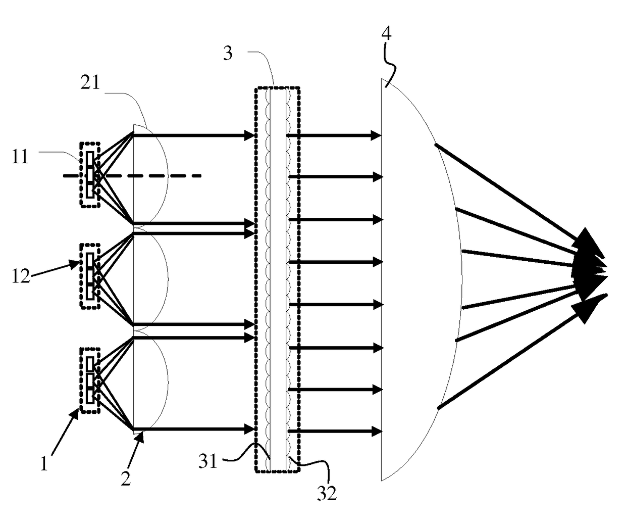
[0038]Refer to FIG. 2, which schematically illustrates the structure of a light source system according to an embodiment of the present invention. The light source system includes a light emitting device 1, a collimating device array 2, a fly-eye lens pair 3 and a focusing lens 4.

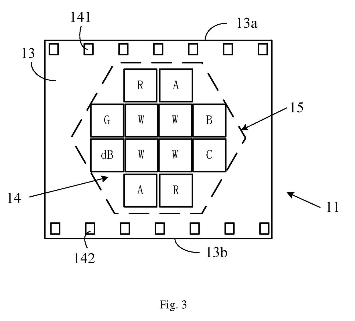
[0039]The light emitting device 1 includes multiple LED unit modules 11 forming an LED unit module array 12. Refer to FIG. 3, which schematically illustrates the structure of an LED unit module 11 in the light source system of FIG. 2. The LED unit module 11 includes a substrate 13 and a LED chipset 14 disposed on the substrate 13. In this embodiment, the substrate 13 is preferably a heat conducting substrate, which can be made of aluminum oxide, aluminum nitride or other heat conducting ceramics, as long as it has sufficiently high thermal conductivity and an insulating surface.

[0040]The LED chipset 14 includes twelve LED chips that are arranged close to each other, and the light emitting surface of th...


PUM


Abstract

An LED unit module, a light-emitting device, and a light source system. The LED unit module comprises a substrate and an LED chipset arranged on the substrate. The LED chipset comprises at least five LED chips, where the LED chips are in a tight arrangement with each other, and the contour of a light-emitting side of the LED chipset is close to a regular hexagon. The LED chipset comprises LED chips of at least four colors, where the four colors are red, blue, green, and amber. The LED unit module allows for prevention of increased etendue and for uniform mixing of lights.

Description

BACKGROUND OF THE INVENTION[0001]Field of the Invention[0002]This invention relates to display and illumination fields, and in particular, it relates to an LED (light emitting diode) unit module, light emitting device, and light source system.[0003]Description of Related Art[0004]Conventional high power illumination devices and lighting apparatus typically uses metal halide discharge lamps as the light sources. Because metal halide discharge lamps are white light sources, when color lights are required, various filter plates are placed in front of the metal halide discharge lamps to generate various color output lights. This type of light sources have the disadvantage that the life of metal halide discharge lamps is low, typically from a few hundred to a few thousand hours; also, color lights generated by filter plates have low color saturation and does not give bright colors, and the colors are not rich.[0005]High power light emitting diodes (LED) has the advantages of safe, non-po...

Claims


Application Information

Patent Timeline
Patent Type & Authority Patents(United States)
IPC IPC(8): F21V5/04F21V14/06F21V13/02H01L33/62H01L25/13H01L25/075F21V23/00F21Y105/10F21Y105/12
CPCF21V5/04F21V13/02F21V14/06H01L25/0753H01L25/13H01L33/62H01L2924/0002F21Y2105/10F21Y2105/12H01L2924/00F21K9/69F21S2/005F21V5/007F21V23/002F21V23/003H05B3/145F21Y2115/10
Inventor ZHANG, QUAN
Owner YLX INC
Why Eureka
Try Eureka