Card edge connector

Inactive Publication Date: 2018-05-15
MITSUBISHI ELECTRIC CORP
View PDF12 Cites 4 Cited by
  • Summary
  • Abstract
  • Description
  • Claims
  • Application Information

AI Technical Summary

Benefits of technology

The present invention aims to provide a card edge connector that can inspect wires without the need for a dummy card, reduce wear and tear, and prevent power-supply short-circuit issues. The connector allows for easy detection of wiring errors and prevents failure caused by abrasion of copper foil terminals. The connector also suppresses slide abrasion of copper foil terminals during pre-use stages.

Problems solved by technology

First, one of the problems in using the dummy card 61C illustrated in FIG. 5C is that it requires labor of mounting and removing the dummy card every time one wire harness is to be inspected.
Further, the dummy card has a short lifetime as inspection equipment for a wire harness being a mass-produced item, with the result that cost for consumption of the dummy card being a spare item is increased.
Further, there is a problem in that chips of a board material or chips of copper foil terminals caused by slide abrasion of the dummy card may enter the card edge connector being a product and move to a control unit connected thereto in a stage of actual use, resulting in degradation of performance and quality of the control unit.
Hei 07-050185, when the contact terminals in the card edge connector have a preliminary contact function, and the circuit board is not inserted, one of problems which may arise in a case where the front and back pair of contact terminals are held in conductive contact with each other is that a separation dimension between the contact terminals increases when the circuit board is inserted, and chips of the board material and chips of the copper foil terminals are caused by the slide abrasion of the circuit board, resulting in degradation of performance and quality of the control unit.
Further, when surface treatment as represented by, for example, gold plating is applied in order to prevent occurrence of contact failure caused by an oxide film on a contact surface, excessive wiping operation may cause separation of a plating layer, resulting in an adverse effect.
Another problem is that, when the control unit is removed by mistake under a state in which a power supply voltage is applied, the preliminary contact terminals may cause a short circuit between the power supply terminals, with the result that a power supply circuit connected to the wire harness is burnt.

Method used


Image

  • Card edge connector
  • Card edge connector
  • Card edge connector

Examples


first embodiment and second embodiment

(1) Detailed Description of Configuration and Action of Card Edge Connector According to First Embodiment

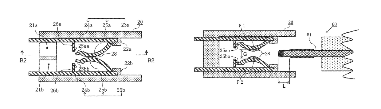
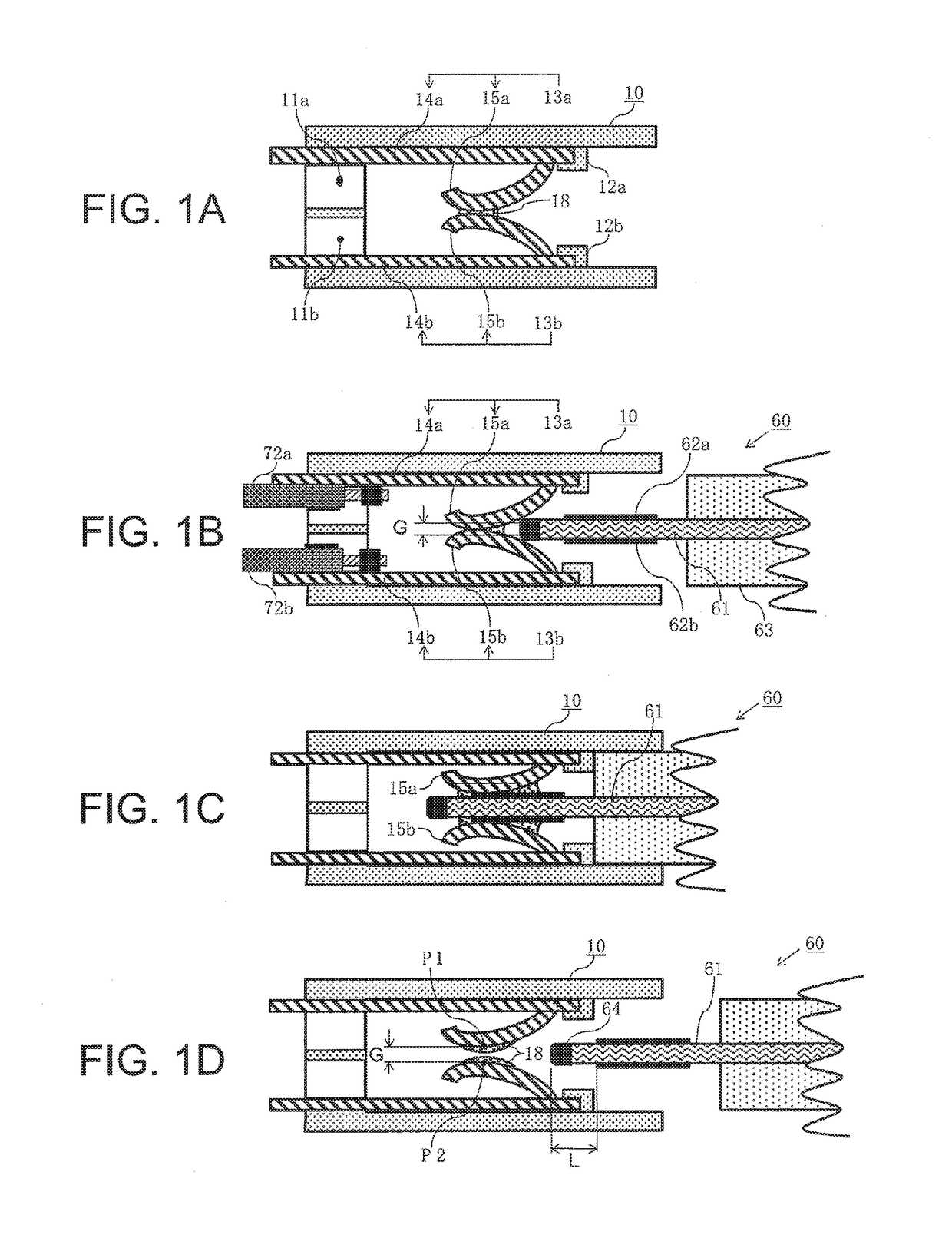
[0049]First, with reference to FIG. 1A being a sectional view for illustrating a card edge connector according to a first embodiment of the present invention, FIG. 1B being a sectional view for illustrating a state immediately before a control unit is inserted into the card edge connector of FIG. 1A, FIG. 1C being a sectional view for illustrating a state in which the control unit is completely inserted into the card edge connector of FIG. 1A, and FIG. 1D being a sectional view for illustrating a state in which the control unit is completely removed from the card edge connector of FIG. 1A, detailed description is made of a configuration and an action of the card edge connector according to the first embodiment.

[0050]In FIG. 1A and FIG. 1B, a card edge connector 10 includes a plurality of front and back pairs of contact terminals 13a and 13b provided in a resin-molded connector ho...

third embodiment and fourth embodiment

(1) Detailed Description of Configuration and Action of Card Edge Connector According to Third Embodiment

[0137]Next, with reference to FIG. 3A being a sectional view for illustrating a card edge connector according to the third embodiment of the present invention, FIG. 3B being a sectional view for illustrating a state immediately before a control unit is inserted into the card edge connector of FIG. 3A, FIG. 3C being a sectional view for illustrating a state in which the control unit is completely inserted into the card edge connector of FIG. 3A, and FIG. 3D being a sectional view for illustrating a state in which the control unit is completely removed from the card edge connector of FIG. 3A, detailed description is made of a configuration and an action of the card edge connector according to the third embodiment.

[0138]In the third embodiment, the card edge connector of the third embodiment is partially changed. Specifically, the mounting positions and directions of movable members...


PUM


Abstract

A plurality of pairs of contact terminals accommodated in a card edge connector include back surface members having one ends to which lead wires are connected and another ends being folded to form movable members. Until a circuit board of a control unit is inserted, end portions of the movable members are held in conductive contact with each other. When the circuit board is inserted, the movable members are separated and brought into contact with copper foil terminals. When the circuit board is removed, the movable members plastically deform and are opposed to each other with an initial gap smaller than a thickness dimension of the circuit board. With this arrangement, wiring inspection may be performed with opposed movable members shorted to one another, but for subsequent circuit board insertion at the second or subsequent insertion and removal of the circuit board, the movable members will be slightly separated by a gap to suppress slide abrasion during insertion.

Description

BACKGROUND OF THE INVENTION1. Field of the Invention[0001]The present invention relates to a card edge connector which is to be used as a part of various connectors connected with a wire harness, and more particularly, to an improved card edge connector which enables easy inspection of presence or absence of erroneous wiring of a plurality of connectors.2. Description of the Related Art[0002]There has been provided a card edge connector, which is mainly constructed by a connector housing formed of a resin-molded material to be removably fixed to a control unit including a plurality of front and back pairs of copper foil terminals provided on both surfaces at an end portion of a circuit board. The card edge connector integrally accommodates a plurality of front and back pairs of contact terminals to be brought into conductive contact with the plurality of pairs of copper foil terminals. The card edge connector is configured to be removably mounted to the control unit. A mating connec...

Claims


Application Information

Patent Timeline
IPC IPC(8): H01R13/50H05K1/14H01R12/72H01R12/70H01R12/73
CPCH01R12/721H01R12/7005H01R12/722H01R12/735H05K1/141H01R13/115H01R13/642H01R12/7094H01R12/75H05K1/117H01R2201/20
Inventor KANZAKI, SHOZOARIMAI, FUMIAKINISHIZAKI, HIROYOSHINAKANISHI, MASATOIGUCHI, SHINGO
Owner MITSUBISHI ELECTRIC CORP
Why Eureka
Try Eureka