
Control method and control system for screw pump

a control method and screw pump technology, applied in machines/engines, liquid fuel engines, boreholes/well accessories, etc., can solve the problems of screw pump losing the ability to control the energy stored in the pump rod, the screw pump cannot be restarted immediately, and the screw pump cannot be stopped immediately, so as to reduce the time period of stopping the screw pump, avoid the effect of backspin in the conventional control system, and release the excess stored potential energy

Active Publication Date: 2018-05-22
DELTA ELECTRONICS INC
View PDF10 Cites 4 Cited by
  • Summary
  • Abstract
  • Description
  • Claims
  • Application Information

AI Technical Summary

Benefits of technology

The present invention provides a control system for a screw pump that can maintain operations even when there is no electrical power. The system uses stored potential energy released by the action of the pump rod to control the backspin of the screw pump, which reduces the time it takes to stop the pump. This avoids the possibility of equipment destruction and enhances personal safety, environmental cleanliness, and productivity.

Problems solved by technology

One of the more significant problems encountered with the pumping operation of the screw pump is the “backspin” that may occur in the event of a momentary electrical power interruption.
When the electrical power is lost, the screw pump loses the ability to control the energy stored in the pump rod due to the oil load thereon.
However, since a very large amount of stored energy still exists in the pump rod of the screw pump, the action of the screw pump is similar to a wound coil spring.
Under this circumstance, the pumping operation of the screw pump cannot be restarted immediately when the electrical power is provided again.
The time period spent during backspin and the time period of waiting for the oil to get back to the ground level (after restarting) will lose productivity.
Consequently, electrical power interruption can cause a significant loss in screw pump productivity.
Since the driving mechanism of the electric motor is often directly connected to the rotor of the screw pump, the electric motor will be subjected to backspin.
Uncontrolled backspin can severely damage the drive mechanism and other production equipment.
In some instances, the backspin may result in equipment destruction.
In addition, if such destruction occurs at the ground level of the well, there exists the possibility of personal injury and environmental contamination.

Method used


Image

  • Control method and control system for screw pump
  • Control method and control system for screw pump
  • Control method and control system for screw pump

Examples


Embodiment Construction

[0018]The present invention will now be described more specifically with reference to the following embodiments. It is to be noted that the following descriptions of preferred embodiments of this invention are presented herein for purpose of illustration and description only. It is not intended to be exhaustive or to be limited to the precise form disclosed.

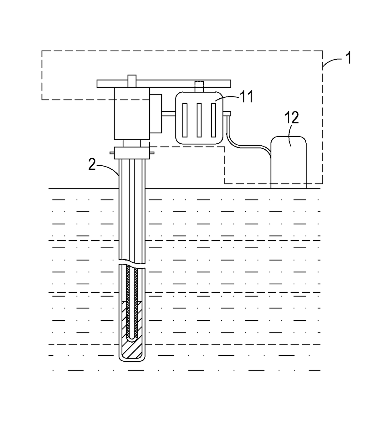
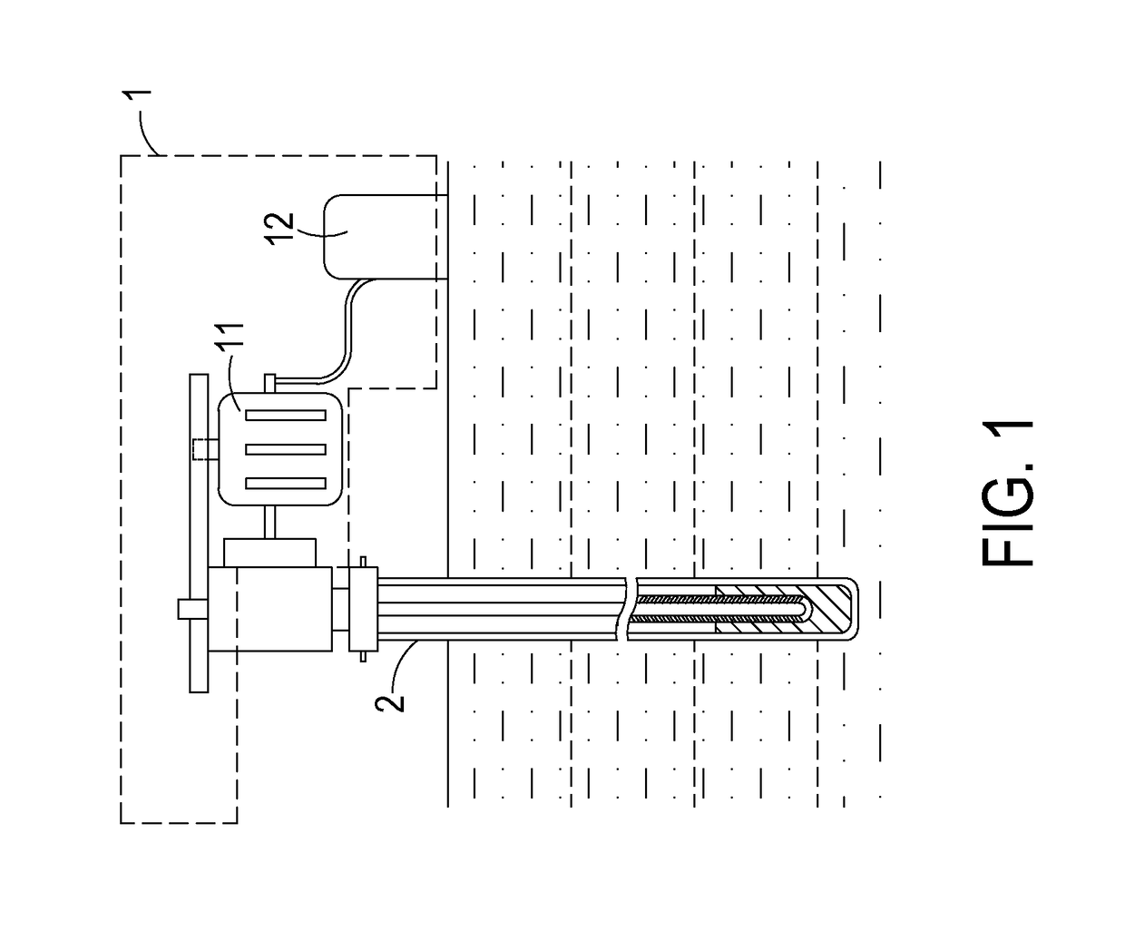
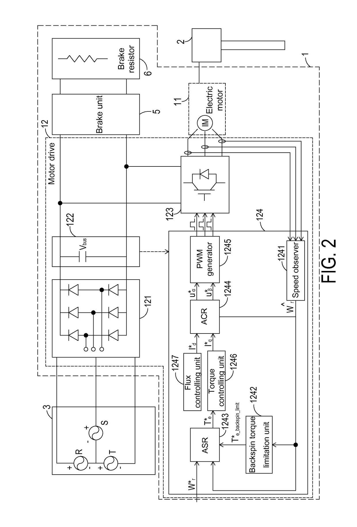
[0019]FIG. 1 is a simplified schematic view of a control system for a screw pump according to an embodiment of the present invention. FIG. 2 is a schematic circuit block diagram of the control system of FIG. 1. As shown in FIGS. 1 and 2, the control system 1 is configured to control and drive the pumping operation of a screw pump 2 for pumping oil from an oil well to a ground level. The structures of the screw pump 2 are similar to those of the conventional screw pump, and are not redundantly described herein. Moreover, the control system 1 comprises an electric motor 11, a motor drive 12 and a brake device. The electric motor 11...


PUM


Abstract

A control method is used with a control system to control a screw pump. The control system includes an electric motor and a motor drive. The control method includes following steps. Firstly, a DC bus voltage is monitored. If the DC bus voltage is smaller than a first threshold value, a potential energy stored in the pump screw and released by a backspin action is converted into a regenerative electrical energy so as to maintain a normal operation of the motor drive. Then, the motor drive drives the electric motor to control the backspin action of the screw pump according to a backspin torque limit strategy. If the electrical power from the power source is not restored and the level of a reverse regenerative torque is smaller than a preset torque value, the backspin action of the screw pump is stopped freely.

Description

CROSS-REFERENCE TO RELATED APPLICATION[0001]This application claims the benefit of U.S. Provisional Application No. 62 / 067,820 filed on Oct. 23, 2014, and entitled “SYSTEM AND METHOD FOR CONTROLLING OPERATION OF SCREW PUMP TO ELIMINATE THE EFFECTS OF BACKSPIN WHEN ELECTRICAL POWER IS LOST”, the entirety of which is hereby incorporated by reference.FIELD OF THE INVENTION[0002]The present invention relates to a control method and a control system, and more particularly to a control method and a control system for a screw pump.BACKGROUND OF THE INVENTION[0003]Screw pumps (also referred to as progressive cavity pumps) are widely used in the oil industry to pump oil from wells. Generally, the operations of the screw pump are controlled by a pump control system including an electric motor and a motor drive. The screw pump comprises a pump rod having a stator and a rotor. The pump rod of the screw pump is physically located deep within the oil well for pumping the oil to the surface. The g...

Claims


Application Information

Patent Timeline
Patent Type & Authority Patents(United States)
IPC IPC(8): F04C13/00F04C2/107E21B43/12F04C14/28
CPCE21B43/126F04C2/1071F04C13/008E21B43/121F04C2270/72F04C2240/403F04C2270/035F04C2270/075F04C14/28
Inventor CHENG, LON-JAY
Owner DELTA ELECTRONICS INC
Learn More