Connecting rod and internal combustion engine

a technology of connecting rods and internal combustion engines, which is applied in the direction of connecting rods, bearings, shafts, etc., can solve the problems of high components and manufacture costs of connecting pins, and achieve the effect of high transmission capacity of compression and tensile forces

Active Publication Date: 2018-05-22
DR ING H C F PORSCHE AG
View PDF9 Cites 1 Cited by
  • Summary
  • Abstract
  • Description
  • Claims
  • Application Information

AI Technical Summary

Benefits of technology

[0010]According to the invention, the second ends of the eccentric rods are designed as spherical heads that engage in a corresponding recess in the respective piston. The piston further accommodates a retention element, such as a retention ring, one segment of which rests on the spherical-head of the respective eccentric rods. Thus, a spherical-seat connection is provided between the eccentric rods and the pistons of the eccentric adjusting device of the connecting rod that are guided in the hydraulic chambers. The spherical-seat connection advantageously provides a degree of freedom in all directions for the articulated attachment of the respective eccentric rod to the respective piston. As a result, any skewing in the attachment of the eccentric rods to the pistons caused by manufacturing and assembly tolerances can be balanced out or compensated. A small axial play and high capacity for transmitting compression and tensile forces can be ensured by the retention element of the spherical-seat connection.
[0012]Each piston and the respective retention element may be composed of a bearing material. Thus, a spherical-seat connection is provided between the eccentric rods and the pistons with a simple construction and lower susceptibility to wear.
[0013]The retention element may be a retention ring slotted at one location on the circumference. The slotted retention ring is advantageous facilitates assembly.
[0014]Each retention element may be snapped into the respective piston so that a segment of the retention element engages around or into an undercut formed on the respective piston. This embodiment allows particularly simple assembly and may dispense with a welded joint or an adhesive joint between the retention element and the piston.

Problems solved by technology

However, the connecting pins require a high outlay on components and on manufacture.

Method used


Image

  • Connecting rod and internal combustion engine
  • Connecting rod and internal combustion engine
  • Connecting rod and internal combustion engine

Examples


Embodiment Construction

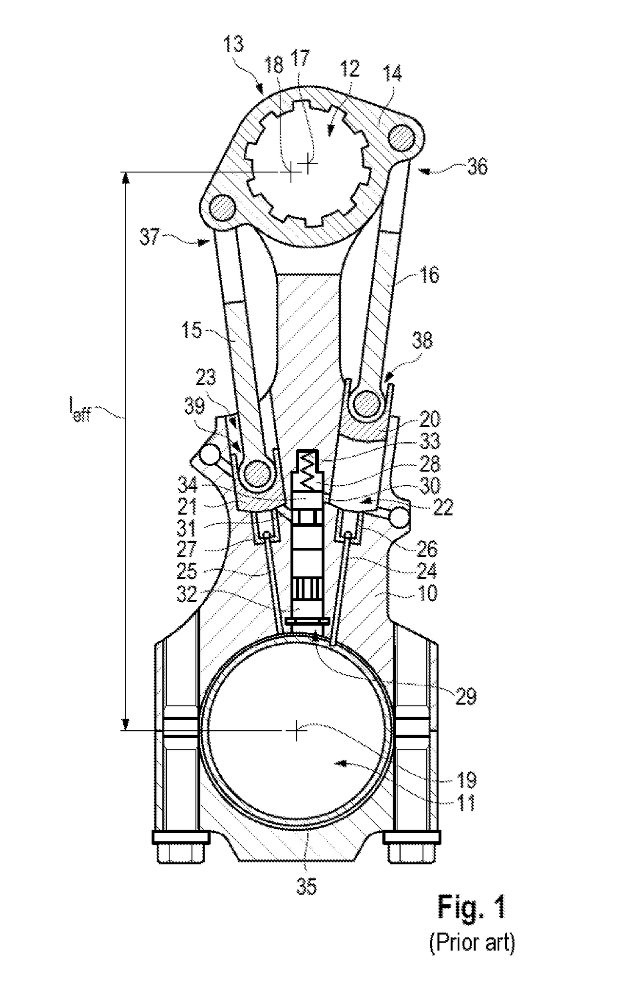
[0019]An internal combustion engine having an adjustable compression ratio has at least one cylinder, and preferably a plurality of cylinders. Each cylinder has a piston that is coupled to a crankshaft of the internal combustion engine by a connecting rod 10. Each connecting rod 10 has a small end bearing eye 12 at one end and a big end bearing eye 11 at an opposite end. The big end bearing eye 11 engages on a crankshaft bearing journal of a crankshaft so that a connecting rod bearing shell is positioned between the crankshaft bearing journal and the big end bearing eye. A lubricating oil film can build up between the connecting rod bearing shell and the crankshaft bearing journal.

[0020]An internal combustion engine having an adjustable compression ratio has an eccentric adjusting device 13 in the region of each connecting rod 10 for adjusting the effective connecting rod length of the respective connecting rod 10.

[0021]The eccentric adjusting device 13 has an eccentric, an eccentri...


PUM


Abstract

A connecting rod has a big end bearing eye for attachment to a crankshaft, a small end bearing eye for attachment to a piston of a cylinder, and an eccentric adjusting device for adjusting an effective connecting rod length. The eccentric adjusting device has eccentric rods (15, 16) with first ends that engage on an eccentric lever of the eccentric adjusting device and second ends that engage on pistons (20, 21) guided in hydraulic chambers of the connecting rod. The second ends of the eccentric rods (15, 16) are spherical heads that engage in a corresponding recess (40) in the respective piston (20, 21), and the respective piston (20, 21) further accommodates a retention element (41), one segment of which rests on the spherical-headed end of the respective eccentric rods (15, 16).

Description

CROSS REFERENCE TO RELATED APPLICATION[0001]This application claims priority under 35 USC 119 to German Patent Appl. No. 10 2015 103 207.4 filed on Mar. 5, 2015, the entire disclosure of which is incorporated herein by reference.BACKGROUND[0002]1. Field of the Invention[0003]The invention relates to a connecting rod for an internal combustion engine and to an internal combustion engine.[0004]2. Description of the Related Art[0005]DE 10 2010 016 037 A1 and FIG. 1 herein show a connecting rod of an internal combustion engine that has an adjustable compression ratio. The connecting rod 10 has a big end bearing eye 11 for attaching the connecting rod 10 to a crankshaft (not shown in FIG. 1) and a small end bearing eye 12 for attaching the connecting rod 10 to a cylinder piston (not shown in FIG. 1) of the internal combustion engine. The connecting rod 10 is used with an eccentric adjusting device 13 that has an eccentric (not shown in FIG. 1), an eccentric lever 14 and eccentric rods 15...

Claims


Application Information

Patent Timeline
Patent Type & Authority Patents(United States)
IPC IPC(8): F02B75/32F16C7/06F16C11/06F02B75/04F16C23/10
CPCF16C7/06F02B75/045F16C11/0623F16C11/069F16C2360/22F16C23/10F02B75/32F02D15/02F01B31/14
Inventor PAUL, MICHAELSCHULTZ, WILLI
Owner DR ING H C F PORSCHE AG
Why Eureka
Try Eureka