Carrier plate for a punching tool

a carrier plate and tool technology, applied in the field of carrier plates for punching tools, can solve the problems of difficult recycling of epoxy resins, relatively high manufacturing cost, and use of non-recyclable epoxy resins in the middle layer of the carrier plate, and achieve the effect of accurately fitting the recesses and long dynamic li

Inactive Publication Date: 2011-01-20
CARL EDELMANN
View PDF6 Cites 0 Cited by
  • Summary
  • Abstract
  • Description
  • Claims
  • Application Information

AI Technical Summary

Benefits of technology

[0008] The object underlying the invention is to provide a carrier plate for a punching tool which can be manufactured at comparably low costs, but has a long dynamic lifetime and in which accurately fitting recesses can be formed by means of a laser.
[0017] Thus the carrier plate according to the invention can be manufactured at relatively little expense, and yet it has all the required properties. Among those are a high dimensional stability even after a large number of punching operations, a low absorption of humidity, a good cutting rule mountability, a high rigidity and compression load capacity as well as a good plane-parallel position at a low thickness tolerance.

Problems solved by technology

A disadvantage of the carrier plate disclosed in DE 203 20 658 U1 is the use of non-recyclable epoxy resins in the middle layer of the carrier plate.
In addition, the materials used are relatively cost-intensive to manufacture.
A disadvantage of such carrier plates is that the recycling of epoxy resins is problematic.
Another disadvantage is a relatively high weight, which results from the use of metals for the upper and lower external layers.
Among other things, this makes it more difficult to handle the carrier plate when installing it in the punch die apparatus.
However, such defectfree veneer plates are cost-intensive.

Method used


Image

  • Carrier plate for a punching tool
  • Carrier plate for a punching tool
  • Carrier plate for a punching tool

Examples


Embodiment Construction

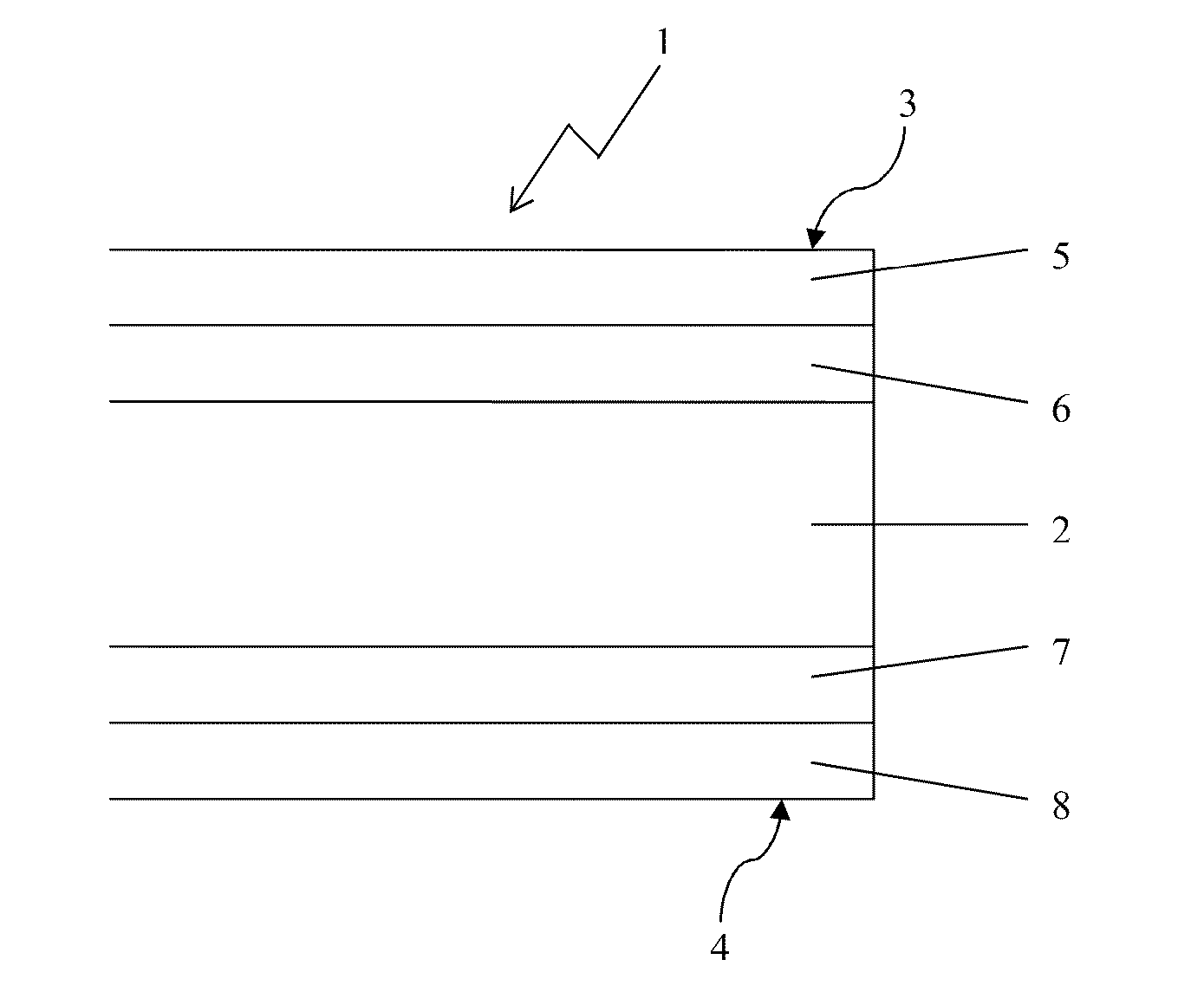
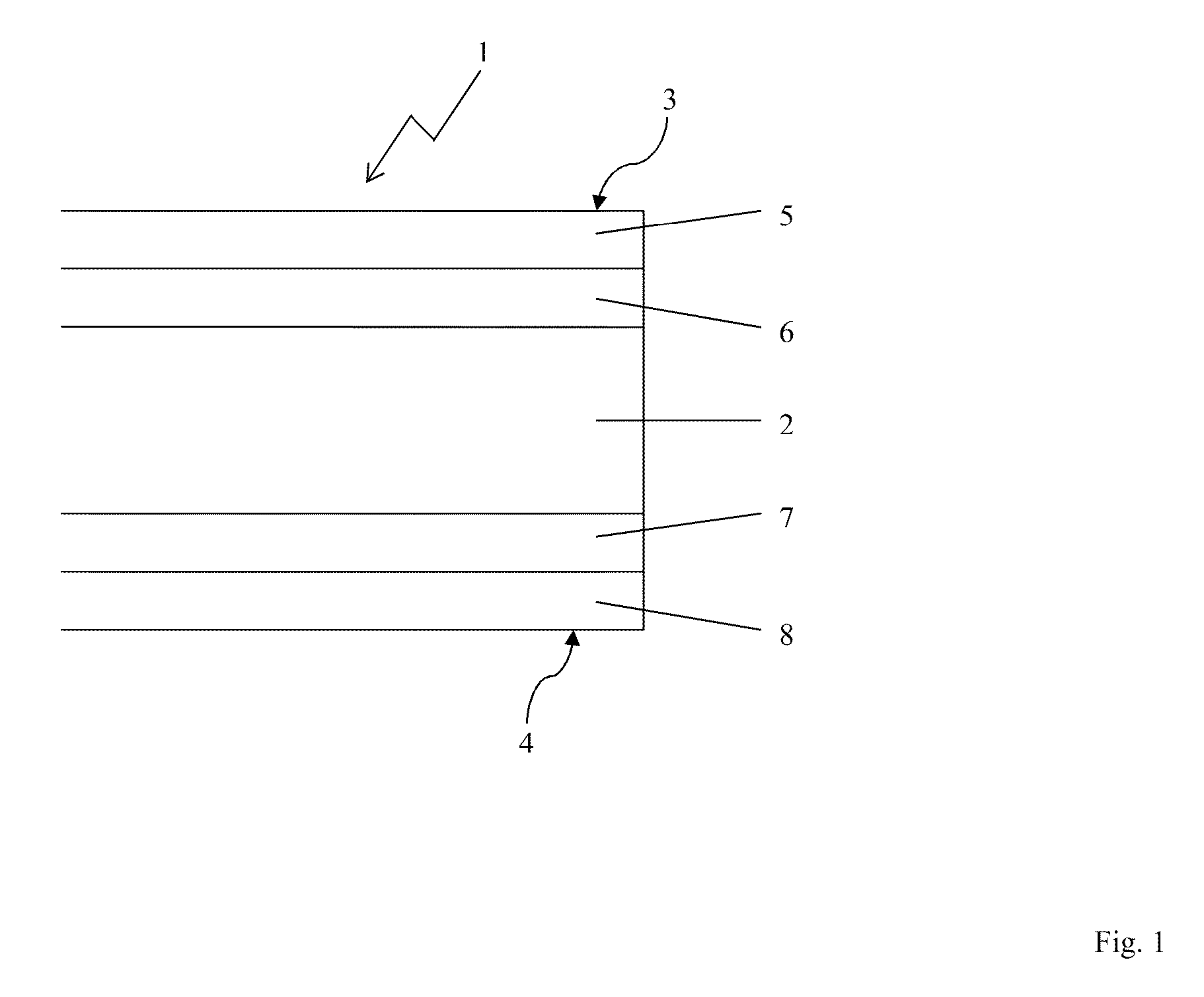
[0022] The carrier plate 1 shown in FIG. 1 has three layers: a middle layer 2 consisting of a plate-shaped MDF wood fiber core and two external layers 3, 4, each of which is formed by two crosswise glued plies 5, 6 and 7,8, respectively, made of birch veneer which is as defect-free and even as possible. The middle layer 2 and the external layers 3, 4 have been glued together by means of a urea glue using pressure and heat, wherein the external layers 3, 4 are glued together cross-wise.

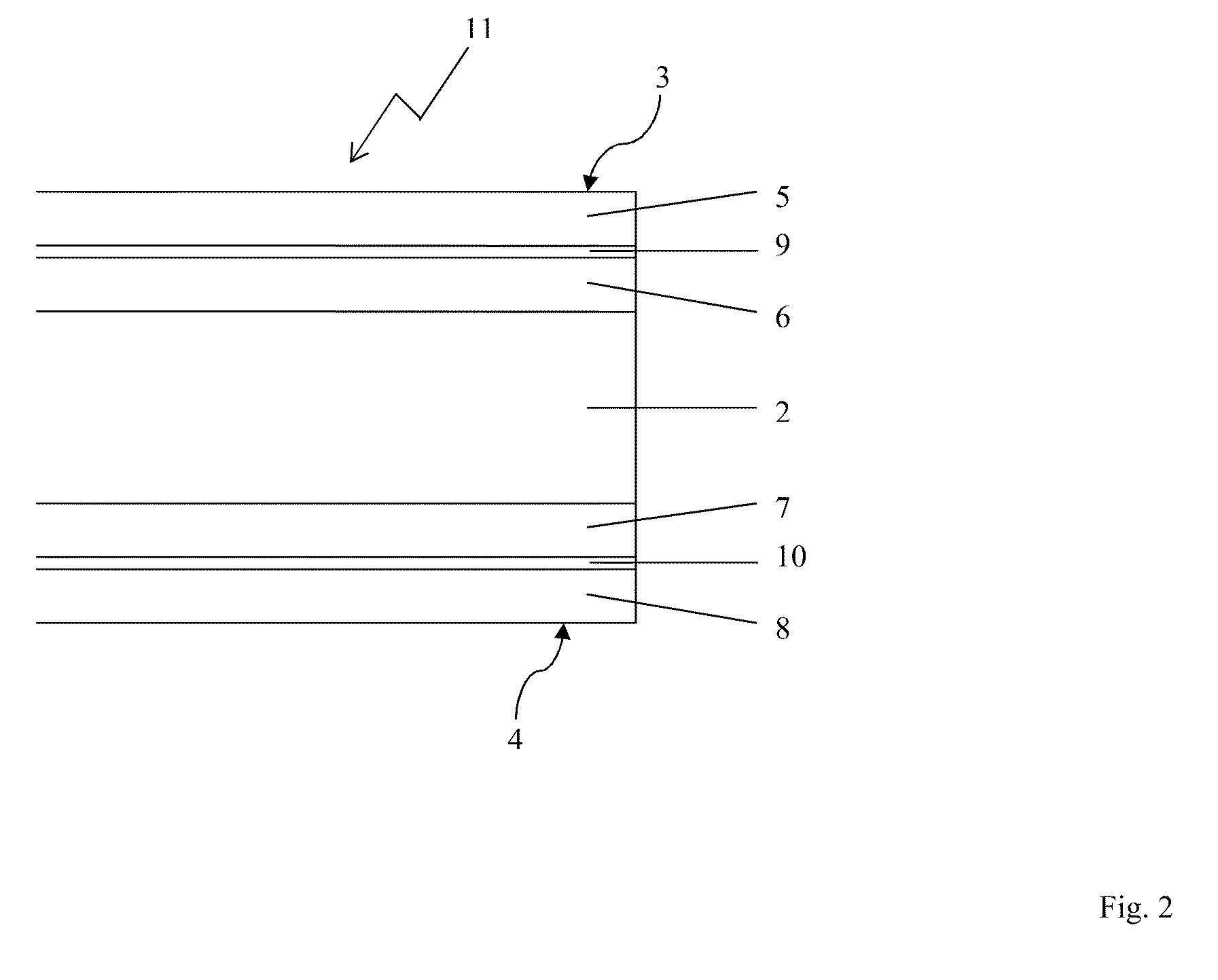
[0023] The carrier plate 11 shown in FIG. 2 differs from the carrier plate 1 shown in FIG. 1 in that between the two plies of birch veneer 5, 6 and 7, 8, respectively, there is a reinforcement 9, made of glass fiber fabric having a mesh width of 1.7 mm and a thickness of 0.3 mm, which reinforcement has been treated with a chromium or silane sizing agent having a thickness of 1 μm. Thereinafter the two plies of birch veneer 5, 6 and 7, 8, respectively, are glued together crosswise with the reinforcemen...


PUM

PropertyMeasurementUnit
thicknessaaaaaaaaaa
thicknessaaaaaaaaaa
thicknessesaaaaaaaaaa

Abstract

A carrier plate (1) for a punching tool includes two external layers (3,4), between which a middle layer (2) is arranged, wherein the middle layer (2) is formed by a core made of compacted fibers and the external layers (3, 4) are formed by wood veneer.

Description

FIELD OF THE INVENTION [0001] The invention relates to a carrier plate for a punching tool having two external layers, between which a middle layer is arranged. DESCRIPTION OF THE BACKGROUND ART [0002] DE 203 20 658 U1 discloses a carrier plate for a punching tool having at least two layers. The middle layer of this carrier plate preferably consists of a foamed plastic, especially epoxy resin. The external layer consists of a compound material made of artificial resin and glass fabric or made of metal. [0003] A disadvantage of the carrier plate disclosed in DE 203 20 658 U1 is the use of non-recyclable epoxy resins in the middle layer of the carrier plate. In addition, the materials used are relatively cost-intensive to manufacture. [0004] Furthermore, it is known to use so-called composite plates as carrier plates in the construction of punch dies. These consist, for example, of a compound made of sheet metal / wood / sheet metal, sheet metal / plastics / sheet metal or sheet metal / sisal, ...

Claims


Application Information

Patent Timeline
Patent Type & Authority Applications(United States)
IPC IPC(8): B32B5/12B32B21/14B32B15/10B32B17/02B32B7/02B32B21/02B32B21/04
CPCB26D2007/2607B26F1/40Y10T428/24967B26F2001/4463Y10T428/24066B26F1/44Y10T428/31703Y10T428/31804Y10T428/31982Y10T428/249921
Inventor MARBACH, PETER
Owner CARL EDELMANN
Why Eureka
Try Eureka