
Optical sensor

a technology of optical sensors and optical sensors, applied in the field of optical sensors, can solve the problems of limiting the achievable accuracy of this type of sensor, relatively sophisticated technology, and relatively expensive components of integrated optical modulators, and achieve the effect of increasing the accuracy of optical sensors

Active Publication Date: 2018-05-29
HITACHI ENERGY LTD
View PDF6 Cites 1 Cited by
  • Summary
  • Abstract
  • Description
  • Claims
  • Application Information

AI Technical Summary

Benefits of technology

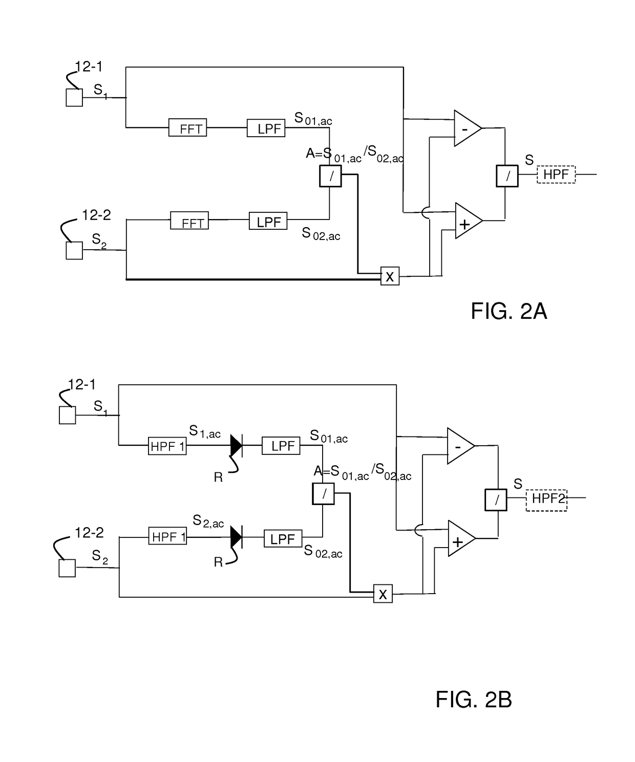
[0009]According to a first aspect of the invention there is provided a method of increasing the accuracy of an optical sensor based on generating two sets of light waves having different velocities in the presence of a non-vanishing measurand field within a sensing element of the sensor and with a defined static bias phase shift introduced between the two sets of light waves, with the sensor converting a total optical phase shift including the static bias optical phase shift and the optical phase shift induced by said measurand field into optical power changes of opposite signs (anti-phase) in at least two detector channels, with the method including the step of normalizing the optical power changes after their conversion into electrical detector signals in two detector channels to reduce the effects of uneven intensity and different loss or gain in the detector channels.

Problems solved by technology

On the other hand the technique is relatively sophisticated and often requires polarization-maintaining (PM) fiber components and elaborate signal processing.
Moreover, integrated-optic modulators are relatively expensive components.
However, asymmetries in the two channels, such as different optical losses, influences of stress, and their variation over time and temperature, limit the achievable accuracy of this type of sensors.
While the sensor accuracy may be sufficient for protection functions in high voltage substations (IEC accuracy class 5P demands an accuracy to within ±1% at the rated current), the accuracy typically is insufficient for electricity metering; the IEC metering class 0.2 for example demands an accuracy to within 0.2% at the rated current (reference [4]).

Method used


Image

  • Optical sensor
  • Optical sensor
  • Optical sensor

Examples


Embodiment Construction

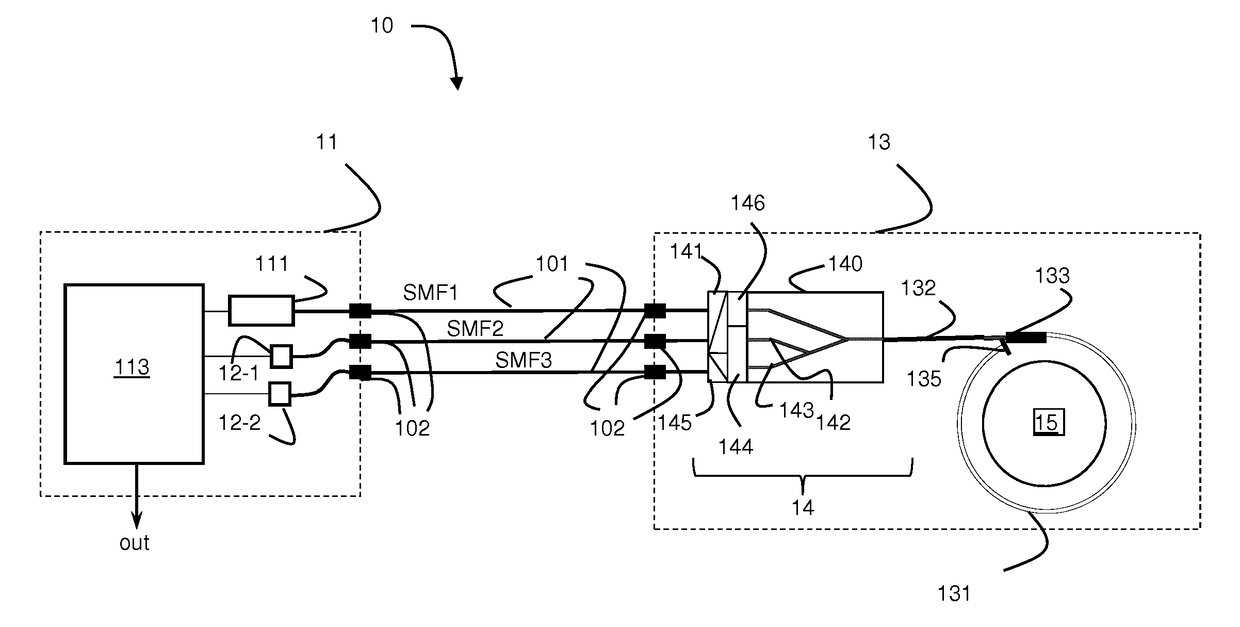
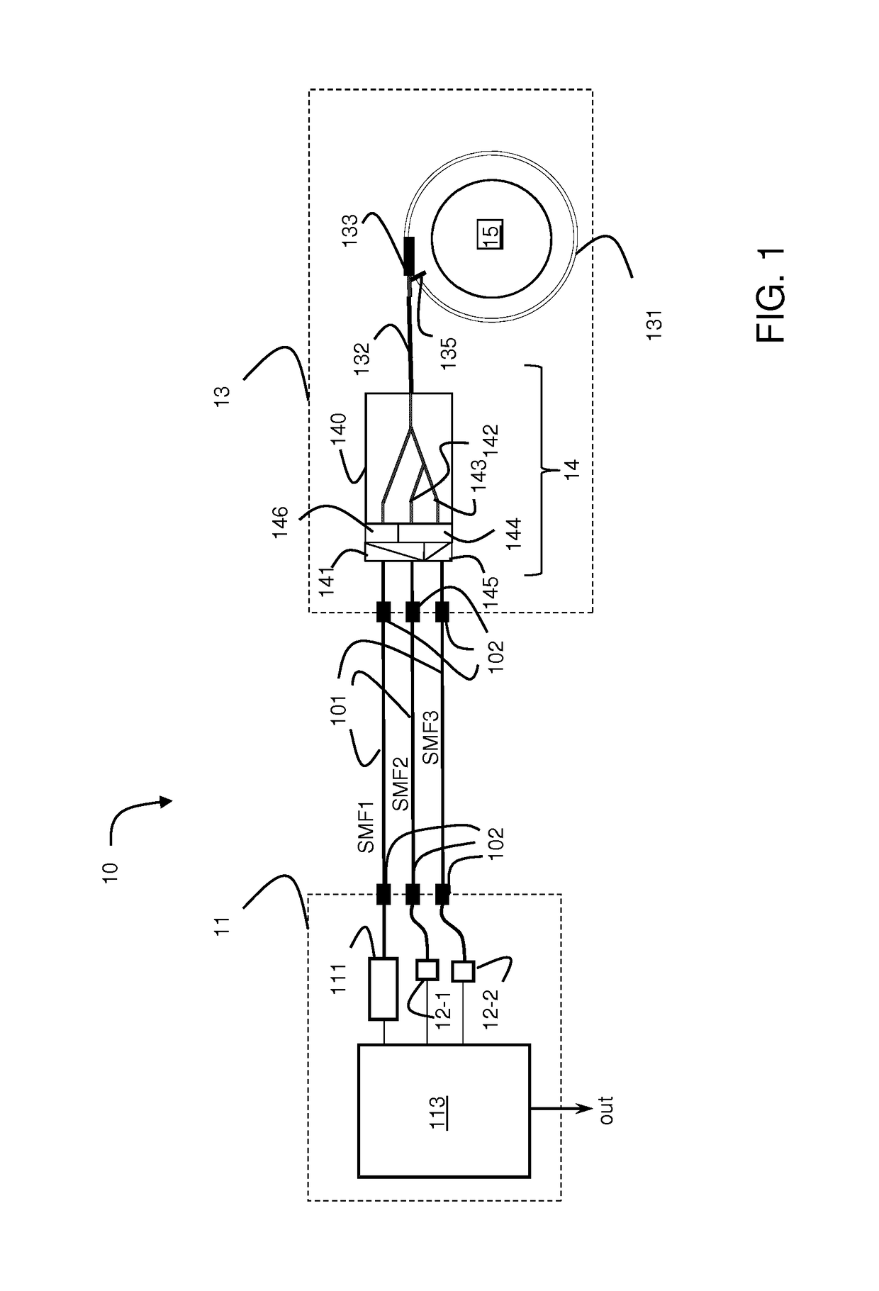
[0033]In FIG. 1 there is shown the example of a configuration of an optical current sensor using a static bias optical phase shift as signal detection scheme. For further details and possible modifications of the known elements of FIG. 1 reference can be made to [3].

[0034]As described further below such sensors with passive elements to introduce a bias phase shift can benefit from the various accuracy-increasing aspects of the present invention to be described below, such as signal processing comprising normalization and filtering of raw signals and additional temperature compensation means.

[0035]In the example of FIG. 1, the sensor 10 includes an opto-electronics module 11 which houses for example a broad-band light source 111, e.g. a superluminescent diode, two photo detectors 12-1, 12-2, and a signal processing unit 113 with power supply and other electronic components (not shown). It is worth noting that any connection between the opto-electronics module 11 and a sensor head 13 ...


PUM


Abstract

A method of increasing accuracy of optical sensors based on generating two sets of light waves having different velocities in the presence of a non-vanishing measurand field within a sensing element of the sensor is described. A defined static bias phase shift is introduced between the two sets of light waves. The sensor converts a total optical phase shift including static bias optical phase shifts and measurand-induced optical phase shifts into anti-phase optical power changes in at least two detector channels. The method includes steps of normalizing the optical power changes after their conversion into electrical detector signals in the two detector channels to reduce effects of uneven intensity or power of the light source and different loss or gain in the detector channels. Further methods, sensors and apparatus for temperature stabilizing such optical sensors and novel sensors are also presented.

Description

FIELD OF THE INVENTION[0001]The disclosure relates to an optical sensor with a sensing element causing a phase shift of light waves passing through it in the presence of a measurand field, such as a fiber optic current sensor (FOCS) or magnetic field sensor that includes a sensing fiber to be exposed to a magnetic field, e.g. of a current to be measured, as typically used in high voltage or high current applications.BACKGROUND OF THE INVENTION[0002]Fiber-optic current sensors rely on the magneto-optic Faraday effect in an optical fiber that is coiled around the current conductor. The current-induced magnetic field generates circular birefringence in the optical fiber that is proportional to the applied magnetic field. A preferred arrangement employs a reflector at the sensing fiber's far end so that the light coupled into the fiber performs a round trip in the fiber coil. Commonly, left and right circularly polarized light waves are injected into the sensing fiber which are generate...

Claims


Application Information

Patent Timeline
Patent Type & Authority Patents(United States)
IPC IPC(8): G01D5/353G01R15/24
CPCG01R15/247G01R15/245G01R15/246G01R33/0322
Inventor BOHNERT, KLAUSFRANK, ANDREASMULLER, GEORGYANG, LIN
Owner HITACHI ENERGY LTD
Learn More