Road finisher with heated tamper bar

Inactive Publication Date: 2018-06-05
BOMAG
View PDF8 Cites 5 Cited by
  • Summary
  • Abstract
  • Description
  • Claims
  • Application Information

AI Technical Summary

Benefits of technology

The invention relates to a configuration for a tamper bar and a piston rod that includes a heating element. The heating element is placed between the piston rod and the tamper bar, providing protection without the need for additional measures. This reduces production costs and allows for easy replacement of the tamper bar without replacing the heating element, saving maintenance costs. Additionally, the method for manufacturing the tamper bar is cost-effective because no additional protection steps are needed. The use of thermal spraying for the application of the heating element offers advantages. Overall, the invention improves the performance and efficiency of the tamper bar and piston rod assembly.

Problems solved by technology

Moreover, if, after a certain operation time, wear renders the tamper bar unusable, it may be replaced without at the same time having to replace the heating element which remains unaffected on the piston rod during replacement of the tamper bar, thereby saving maintenance costs.

Method used


Image

  • Road finisher with heated tamper bar
  • Road finisher with heated tamper bar
  • Road finisher with heated tamper bar

Examples


Embodiment Construction

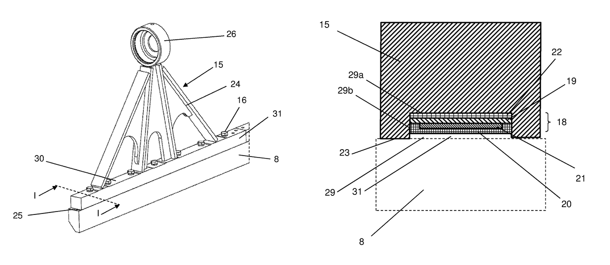
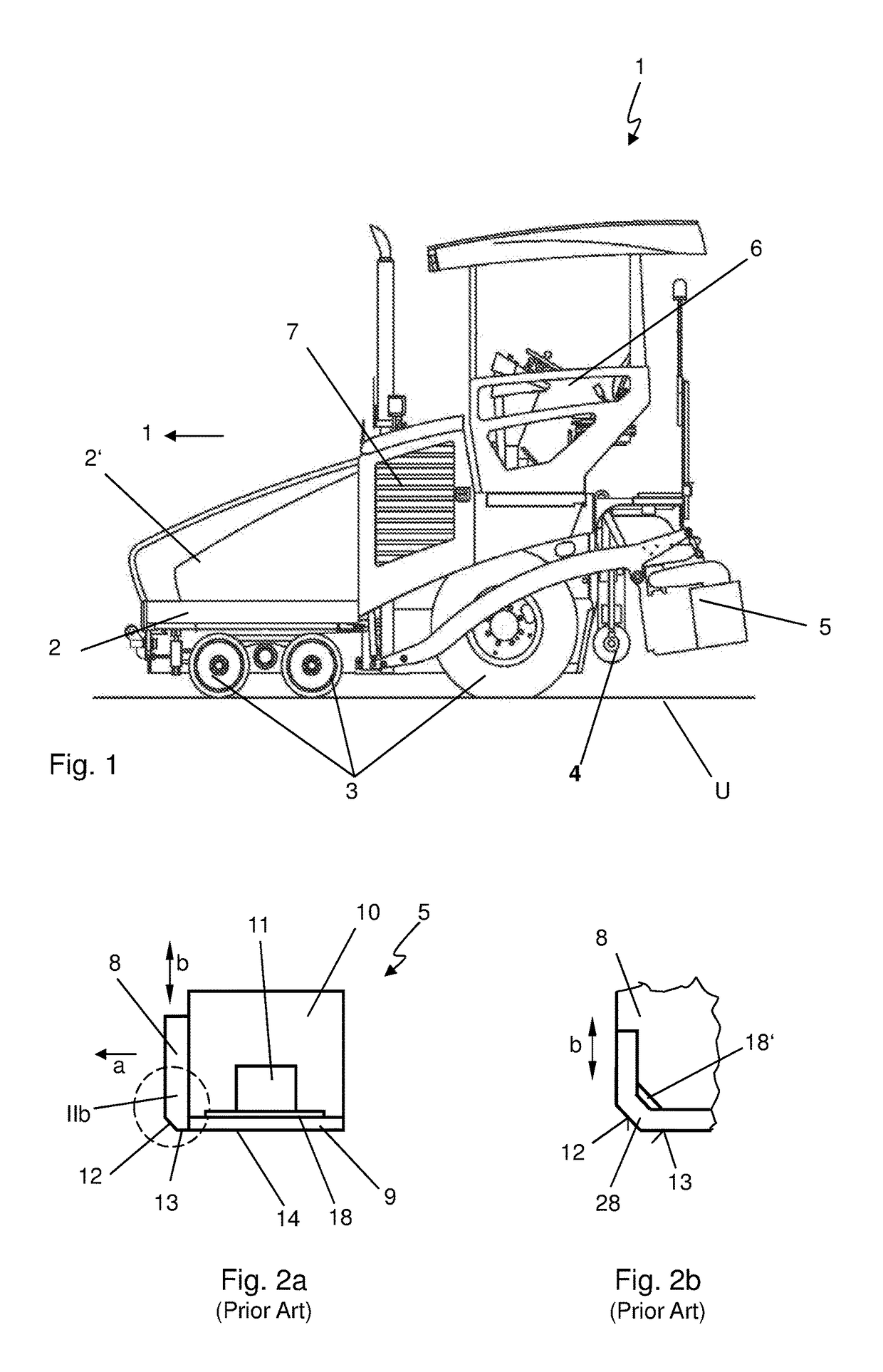
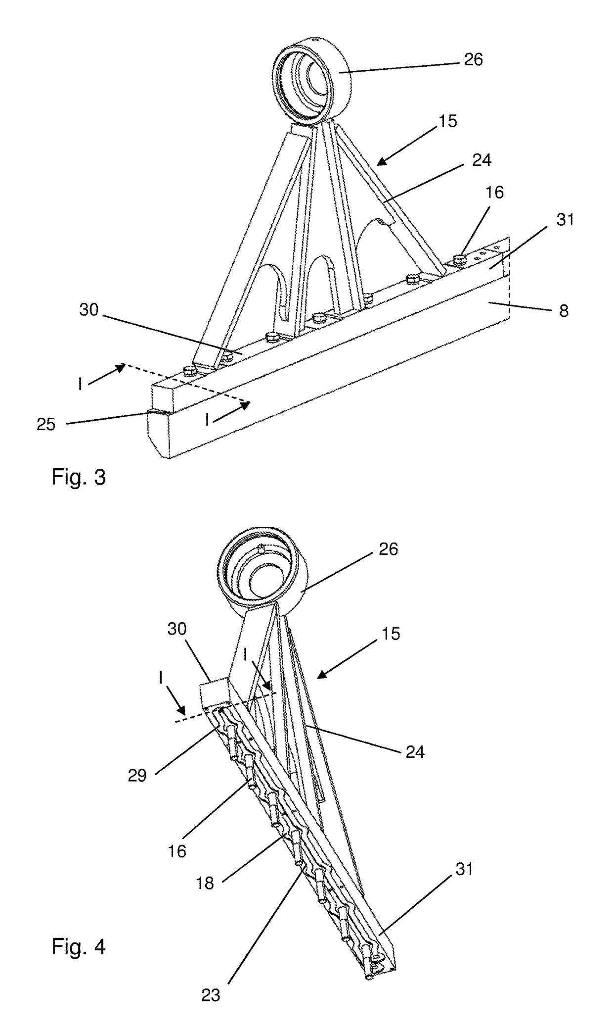
[0037]As shown in FIG. 1, the essential components of the road finisher 1 are a machine frame 2, driving devices 3 for the traveling operation (track systems can also be used in this context, in part), a bunker 2′ for accommodating paving material, a transporting unit (not shown in detail), by means of which the paving material accommodated in the bunker is transported rearwardly contrary to the working direction “a” to the paving section, a spreading screw 4, by means of which the paving material is distributed across the paving width of the road finisher 1 at right angles to the working direction “a”, and a paving screed 5 that is trailed after the road finisher 1 during the paving operation in a floating manner on the bituminous paving material. The paving screed is mounted on the road finisher 1 so as to be vertically displaceable and can be lowered from its raised starting position towards the road subsurface for execution of the operating mode. Furthermore, a control platform ...


PUM

PropertyMeasurementUnit
Lengthaaaaaaaaaa
Velocityaaaaaaaaaa

Abstract

A road finisher includes a screed plate extending at right angles to the working direction of the road finisher, a tamper bar disposed rearwardly and / or forwardly of the screed plate in the working direction, wherein at least one electrically operated heating element is configured to heat up a heating surface facing a road subsurface, the heating element comprising a heating layer at least partially obtained through thermal spraying onto a substrate surface, and a piston rod with connecting means to a tamper bar drive. The tamper bar is connected to the piston rod with an upper surface of the tamper bar contacting a lower surface of the piston rod, wherein the piston rod is single-pieced with regard to its connecting means and its lower surface, and the heating layer is located between the piston rod and the tamper bar, especially applied to the lower surface of the piston rod.

Description

FIELD[0001]The present application generally relates to a road finisher comprising a screed plate and a tamper bar, the tamper bar being heated by a heating element, and more particularly, relates to a piston rod for a road finisher and a method of manufacturing an assembly of a piston rod and a tamper bar.BACKGROUND[0002]Road finishers or asphalt finishers are construction machines for producing asphalt surfaces, also known as pavers. In operation, the road finisher distributes and smoothes bituminous paving material, and may also compact the same. For this, the road finisher basically is equipped with a screed plate for smoothing the paving material, and a tamper bar for pre-compacting the paving material before it is smoothed. In order to prevent sticking of the bituminous paving material to the paving device, heating devices are employed which heat up the tamper bar and / or the screed plate and which may be implemented on the tamper bar and / or the screed plate, for example, as a ...

Claims


Application Information

Patent Timeline
IPC IPC(8): E01C19/40E01C19/48C23C4/06C23C4/126C23C4/134C23C4/10E01C19/30F16M13/02
CPCE01C19/405C23C4/06C23C4/10C23C4/126C23C4/134E01C19/4833F16M13/02E01C19/30E01C2301/10E01C19/40E01C19/486
Inventor CAPUTO, GIANLUCA
Owner BOMAG
Why Eureka
Try Eureka