Airplane with variable-incidence wing

a variable-incidence, aircraft technology, applied in the direction of vertical landing/take-off aircraft, wing shapes, transportation and packaging, etc., can solve the problems of unacceptably high drag (drag due to lift), waste of weight, and relatively complex allen and spratt craft, so as to save weight, the effect of being smaller and lighter

Inactive Publication Date: 2000-01-11
JOAO VERDI CARVALHO LEITE
View PDF65 Cites 43 Cited by
  • Summary
  • Abstract
  • Description
  • Claims
  • Application Information

AI Technical Summary

Benefits of technology

Thus, compared with the Allen or Spratt craft, the "break" in the wing is arranged differently--in such a way that wing bending moments are resisted by the long hinge, instead or being carried on a single short shaft. This saves weight, since the hinge pin can be made smaller and lighter than a shaft.

Problems solved by technology

This small causes span the cruise induced drag (drag due to lift) to be unacceptably high.
Allen's and Spratt's craft are relatively complex in that each requires a separate horizontal tail.
The wing bending moments are carried on a shaft; this wastes weight, because the shaft must be relatively large and heavy.

Method used


Image

  • Airplane with variable-incidence wing
  • Airplane with variable-incidence wing
  • Airplane with variable-incidence wing

Examples


Embodiment Construction

1. General Configuration and Operation

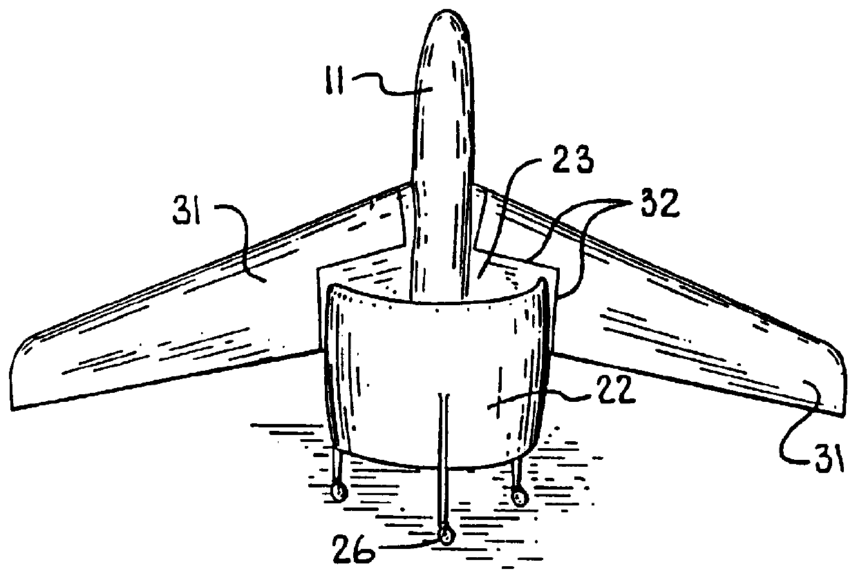
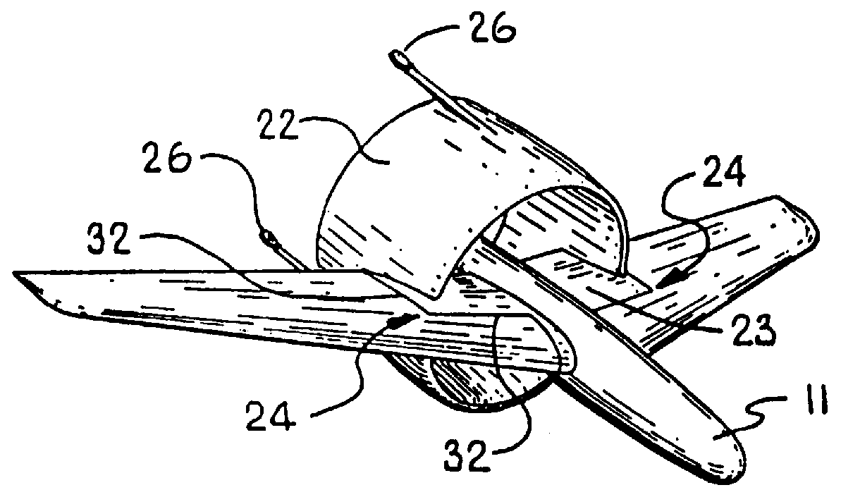
The configuration of my contemplated vehicle is shown in FIGS. 1 through 6. Thrust is provided by an aft-mounted, ducted 22, preferably contrarotating fan 21 (FIG. 4). Vanes 25 in the fan efflux provide control about all three axes in cruise as well as when the vehicle is hovering.

The wing 31 is pivoted along an approximately spanwise axis 24 (FIG. 1), allowing the wing to vary in angle of attack. There are at least three wing-incidence control options:

fully-floating wing;

floating wing which couples with body or fuselage 11 incidence at low angles of attack; and

wing incidence controlled by actuators and scheduled by a flight-control system.

In the first of these options, the combination of hinge axis 24 and wing pitching-moment coefficient at zero lift are tailored so that the wing tends to float at a lift coefficient near the maximum value.

In the second option, stops are arranged so that the wing may only float leading-edge-down relative to the ...


PUM


Abstract

The craft is for hovering flight, vertical takeoff and landing, and horizontal forward flight. It has a tail-sitting fuselage and a ducted fan mounted to the fuselage aft to provide propulsion in both (a) hovering and vertical flight and (b) horizontal forward flight. At each side is a floating wing, supported from the fuselage for passive rotation (or an actuator-controlled optimized emulation of such rotation) about a spanwise axis, to give lift in forward flight. The fuselage attitude varies between vertical in hovering and vertical flight, and generally horizontal in forward flight. Preferably the fuselage is not articulated; there is just one fan, the sole source of propulsion, rotating about only an axis parallel to the fuselage; and thrust-vectoring control vanes operate aft of the fan. Preferably at each side a small, nonrotating wing segment is fixed to the fuselage, and the floating wing defines-along its trailing portions-a corner notch or slot near the fuselage; forward portions of the fixed wing segment are within this notch. Preferably the spanwise axis is along a surface of the floating wing, and a long hinge supports that wing from the fixed wing segment, within the notch. During vertical and transitional flight characteristically the leading edge of the floating wing is down relative to the fuselage axis.

Description

BACKGROUND1. Field of the InventionThis invention relates generally to vertical-takeoff-and-landing (VTOL) airplanes; and more particularly to tail-sitting aircraft capable of hovering flight, generally vertical takeoff and landing, and substantially horizontal forward flight.2. Prior ArtTwo types of prior aircraft are pertinent to my invention:ducted -fan craft, such as the French Coleopter (FIG. 8) and the 1972 Shorts Skyspy; and"free wing" or "floating wing" craft in which the wing pivots about a spanwise axis, and is free to float in response to gusts. FIGS. 9 through 12 show a craft of this type, designed by Spratt.In operation near hover, for a given diameter and power, a ducted fan produces more static thrust than an unducted propeller. The Coleopter enjoys this important advantage. Following is an excerpt from Taylor, J. W. R., ed., Jane's Pocket Book of Research & Experimental Aircraft (1976), at page 221, on the "SNECMA C.450-01 Coleopterere". FIG. 8 has been adapted from ...

Claims


Application Information

Patent Timeline
Patent Type & Authority Patents(United States)
IPC IPC(8): B64C39/06B64C29/00B64C29/02B64C3/38B64C39/00B64C3/00
CPCB64C3/385B64C29/02B64C39/062
Inventor WAINFAN, BARNABY
Owner JOAO VERDI CARVALHO LEITE
Why Eureka
Try Eureka