Method of fabricating an electroacoustic transducer

Inactive Publication Date: 2000-01-18
FOSTER ELECTRIC CO LTD
View PDF4 Cites 11 Cited by
  • Summary
  • Abstract
  • Description
  • Claims
  • Application Information

AI Technical Summary

Benefits of technology

Further, in case the method of fabricating the electroacoustic transducer employs a coil formed by winding a wire as an individual air-core coil in advance, such a coil may be merely mounted on a pole portion or core of the pole piece portion on the lead frame, which reduces an assembling time. Still further, when the coil is wound around the pole portion or core of the pole piece portion on the lead frame, the coil can be formed on the l

Problems solved by technology

However, this makes the makes proc

Method used


Image

  • Method of fabricating an electroacoustic transducer
  • Method of fabricating an electroacoustic transducer
  • Method of fabricating an electroacoustic transducer

Examples


first embodiment

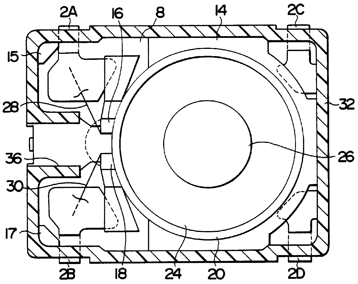
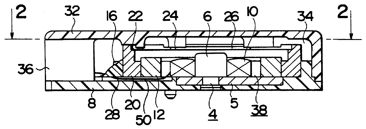
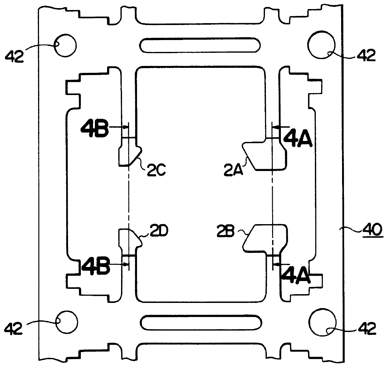
FIGS. 1 and 2 show an electroacoustic transducer fabricated in accordance with the present invention. Lead terminals 2A, 2B, 2C and 2D are integrally formed of a lead frame 40. A pole piece portion 4 consists of a plate-shaped yoke 5 and a core 6 attached to the yoke 5. The lead terminals 2A, 2B, 2C and 2D and the pole piece portion 4 are embedded in a base 8 formed of a synthetic resin in the shape of a rectangular flat plate.

A coil 10 is wound around the core 6, and an annular magnet 12 is disposed so as to surround the coil 10. The magnet 12 and the pole piece portion 4 are magnetically coupled to form a magnetic path. The coil 10 formed of an air-core one is mounted on the core 6 or directly wound around the core 6.

The base 8 is provided on its upper surface with positioning protrusions 14, 15, 16, 17 and 18. A support ring 20 is positioned inside the positioning protrusions 14, 16 and 18 on the base 8. The support ring 20 has a stepped portion 22 on its inner surface at a posit...

case 32

A case 32 is positioned in place on the base 8 by the positioning protrusions 14, 15 and 17, and the case 32 is fixed to the base 8 by a fixing means, such as ultrasonic welding. The case 32 formed of synthetic resin defines a resonance space 34 extending over the surface of the diaphragm 24 and around the support ring 20. The case 32 is provided on one side wall thereof with a sound emitting cylinder 36 by means of which the resonance space 34 communicates with the atmosphere.

In such an electroacoustic transducer, the pole piece portion 4 having the core 6 and combined with the base 8 by insert molding, the coil 10 and the magnet 12 constitute an electromagnetic transducing portion 38. When an ac signal is applied across the lead terminals 2A and 2B, the coil 10 is excited and creates an alternating magnetic field between the core 6 and the diaphragm 24 provided with the magnetic piece 26. Consequently, the diaphragm 24 vibrates to generate sound, the resonant space 34 resonates an...


PUM


Abstract

The present invention provides a fabrication method of an electroacoustic transducer capable of simplifying an assembling process on a lead frame and realizing an automatic assembly. The method comprises steps of forming pole piece portions, forming a lead frame having a plurality of base forming areas thereon, each of the areas having lead terminals formed therein, forming bases of a synthetic resin on the lead frame by molding so that the pole piece portions are embedded in the bases, mounting a coil on the pole piece portions embedded in the bases, disposing a support ring and a magnet so as to surround the coil, and placing a diaphragm on the support ring to be held thereby, connecting opposite ends of the coil to the lead terminals, cutting off the lead terminals from the lead frame, putting cases on and fixedly joining the same to the bases, and subjecting the cut lead terminals to a forming process.

Description

BACKGROUND OF THE INVENTION1. Field of the InventionThe present invention relates to a method of fabricating an electroacoustic transducer for converting electric input signals into sound.2. Description of the Prior ArtElectroacoustic transducers are employed in various miniature electronic devices, such as card-shaped portable pagers. Miniaturization of electroacoustic transducers to be incorporated into such miniature electronic devices has been requested and efforts have been made for the further miniaturization of the component parts of electroacoustic transducers.FIGS. 16 and 17 show an example of a conventional electroacoustic transducer. The construction of and a method of fabricating this conventional electroacoustic transducer will be described. A cylindrical upper case 102 and a cylindrical lower case 104 are formed individually of a synthetic resin by molding. A yoke 106 is attached to the lower side of the lower case 104 and a base plate 108 is attached to the lower surf...

Claims


Application Information

Patent Timeline
IPC IPC(8): H04R31/00
CPCH04R31/006H04R13/00Y10T29/49005
Inventor SONE, TAKAHIRO
Owner FOSTER ELECTRIC CO LTD
Why Eureka
Try Eureka