Transmission diversity for a CDMA/TDD mobile telecommunication system

a mobile telecommunication system and transmission diversity technology, applied in the field of mobile telecommunication systems, can solve the problems of affecting the quality of communication, and becoming a degradation factor of the transmission system, so as to improve communication quality, improve communication quality, and improve communication quality.

Inactive Publication Date: 2000-02-29
PANASONIC INTELLECTUAL PROPERTY CORP OF AMERICA
View PDF10 Cites 64 Cited by
  • Summary
  • Abstract
  • Description
  • Claims
  • Application Information

AI Technical Summary

Benefits of technology

Therefore, according to the present invention, in the reverse link, an antenna by which an electric field having a good level is received is selected, whereby it is possible to maintain always a communication link in a good state. In addition, by increasing the number of antennas, even the request for the high communication quality can be satisfied. Further, since the correlation of the transmission path of the reverse link and that of the forward link is high, in the forward link as well, the same effects can be obtained.
In addition, since the transmission path or link states are different among the mobile stations, a transmission / reception antenna is selected for every link leading to the associated mobile station, whereby the interference due to the communication radio waves of other mobile stations is relatively reduced. As a result, since the communication quality is improved, and also the transmission power can be reduced, the mobile station can be miniaturized and lightened.

Problems solved by technology

This becomes a degradation factor of the transmission system.
(1) Since the correlation between the fading of the forward link and that of the reverse link is small, the space diversity technique in the base station can be applied to only the reverse link.
(2) In the case where the received power is reduced due to frequency selective fading, the communication quality is degraded and hence it is difficult to perform high quality communication.
(3) In the case where the communication capacity has greatly increased, since the interference of the communication radio waves of other stations with the communication radio wave of the local station becomes large, the communication quality is degraded, and hence it is difficult to perform high quality communication.
(4) In the case where the communication capacity has greatly increased, the requirements on the quadrature modulator and the linear amplifier of the base station become severe.

Method used


Image

  • Transmission diversity for a CDMA/TDD mobile telecommunication system
  • Transmission diversity for a CDMA/TDD mobile telecommunication system
  • Transmission diversity for a CDMA/TDD mobile telecommunication system

Examples


first embodiment

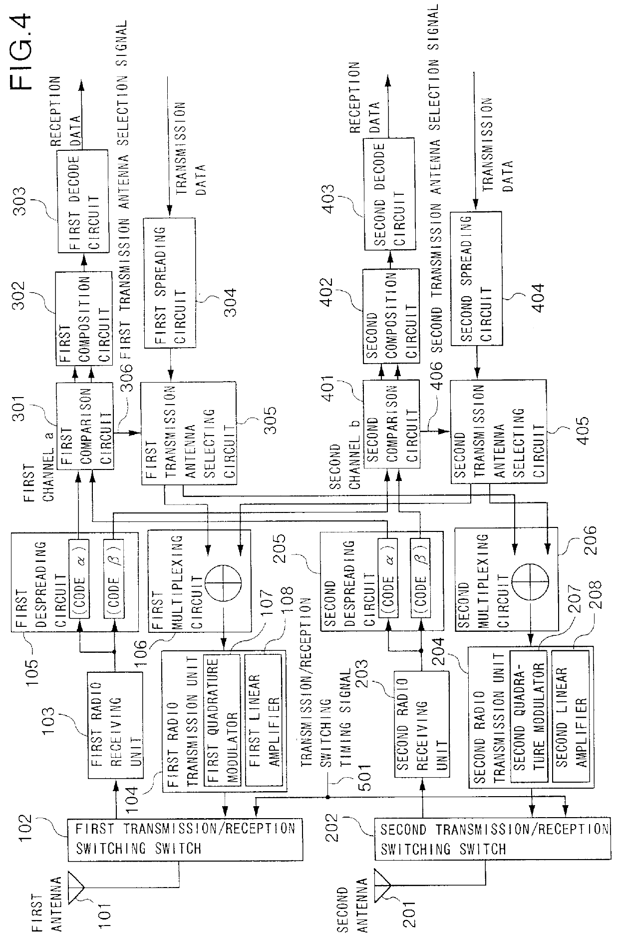
FIG. 4 shows the configuration of a base station of a mobile telecommunication system according to a first embodiment of the present invention, and in this example the base station has two antennas and two channels a and b. In FIG. 4, reference numeral 101 designates a first antenna (an antenna A), reference numeral 201 designated a second antenna (an antenna B), reference numeral 102 designates a first transmission / reception switching switch for the first antenna 101, reference numeral 202 designates a second transmission / reception switching switch for the second antenna 201, reference numeral 103 designates a first radio receiving unit for the first antenna 101, and reference numeral 203 designates a second radio receiving unit for the second antenna 201. Reference numeral 105 designates a first despreading circuit for the first antenna 101, and reference numeral 205 designates a second despreading circuit for the second antenna 201. Each of the first and second despreading circui...

second embodiment

FIG. 6 shows the configuration of a base station of a mobile telecommunication system according to a second embodiment of the present invention, and also shows an example in which the base station has two antennas and two channels a and b. In FIG. 6, reference numeral 101 designates a first antenna (an antenna A), reference numeral 201 designates a second antenna (an antenna B), reference numeral 102 designates a first transmission / reception switching switch for the first antenna 101, reference numeral 202 designates a second transmission / reception switching switch for the second antenna 201, reference numeral 103 designates a first radio receiving unit for the first antenna 101, and reference numeral 203 designates a second radio receiving unit for the second antenna 201. Reference numeral 105 designates a first despreading circuit for the first antenna 101, and reference numeral 205 designates a second despreading circuit for the second antenna 201. In this connection, each of the...

third embodiment

The configuration of a base station of a mobile telecommunication system according to the present embodiment is the same as that in the second embodiment. FIG. 8 shows an example of an antenna arrangement of the base station of the mobile telecommunication system in the present embodiment, and also shows an example in the case where three antennas A, B and C are provided. With respect to the antennas A, B and C, any two antennas are separated enough to obtain independently fading transmission links, and they are arranged in the central portion of the cover area of the base station to provide generally concentric coverage.

In mobile telecommunication, the fluctuations in the power level of the received signal are roughly due to the following three factors.

(1) Change caused by distance: Fluctuations in the reception level due to a change in the communication distance caused by movement of the mobile station.

(2) Change in central value: Fluctuations in the reception level due to a chang...


PUM


Abstract

In a base station which has a plurality of antennas, each of a plurality of comparison circuits operates to compare correlation levels, which are obtained by despreading received signals for a plurality of channels, with each other with respect to the antennas. Each of a plurality of transmission antenna selecting circuits operates to determine from which antenna a transmission signal is to be transmitted for every channel. Each of a plurality of multiplexing circuits operates to multiplex the transmission signals of the individual channels, which are spread, for every antenna. As a result, on the basis of the result of the comparison of the correlation levels with respect to the antennas, a transmission antenna is selected for every channel, and the signals of the channels that are to be transmitted by a given antenna are multiplexed, whereby the base station achieves transmission diversity.

Description

BACKGROUND OF THE INVENTION1. Field of the InventionThe present invention relates to a mobile telecommunication system which is adapted to secure a communication link for a mobile unit moving in a wide area by utilizing wireless communications, and more particularly to a mobile telecommunication system which is adapted to perform communication by utilizing a CDMA / TDD system adopting the direct sequence spread spectrum (DS-SS) system.2. Description of the Related ArtA system in which communication is established among a plurality of stations in the same frequency band is called a multiple access system. CDMA (Code Division Multiple Access) is a technology in which the multiple access is performed on the basis of spread spectrum communication, in which an information signal is transmitted with the spectrum thereof spread into a sufficiently wider band than the band width of the information signal of the unit. A DS-SS system is a system wherein in the spreading, the information signal ...

Claims


Application Information

Patent Timeline
Patent Type & Authority Patents(United States)
IPC IPC(8): H04B7/26H04B7/04H04W16/28H04B1/707H04B1/7115H04B7/06H04B7/08H04J13/00
CPCH04B7/04H04B7/0608H04B7/2618
Inventor HAYASHI, MASAKIMIYA, KAZUYUKIKATO, OSAMU
Owner PANASONIC INTELLECTUAL PROPERTY CORP OF AMERICA
Why Eureka
Try Eureka