Visible light and infra-red cooking apparatus

Inactive Publication Date: 2000-06-06
GENERAL ELECTRIC CO
View PDF99 Cites 42 Cited by
  • Summary
  • Abstract
  • Description
  • Claims
  • Application Information

AI Technical Summary

Benefits of technology

One or more of the radiation source lamps may be used in the cooking process as necessary. These radiation sources are ordinarily positioned above and below the food item. Certain applications may require that radiation sources surround the food item. The walls of the surrounding food chamber are preferably treated to be highly reflective. The visible and infrared waves from the radiation sources impinge directly on the food item and are also reflected on t

Problems solved by technology

It has generally been believed that radiation with wavelengths much shorter than 1 .mu.m is not of much value in cooking or baking processes, partly because of the weaker interaction of the shorter wavelengths with the foodstuff molecules in terms of general heat transfer, and partly due to the inferior pe

Method used


Image

  • Visible light and infra-red cooking apparatus
  • Visible light and infra-red cooking apparatus

Examples


Example

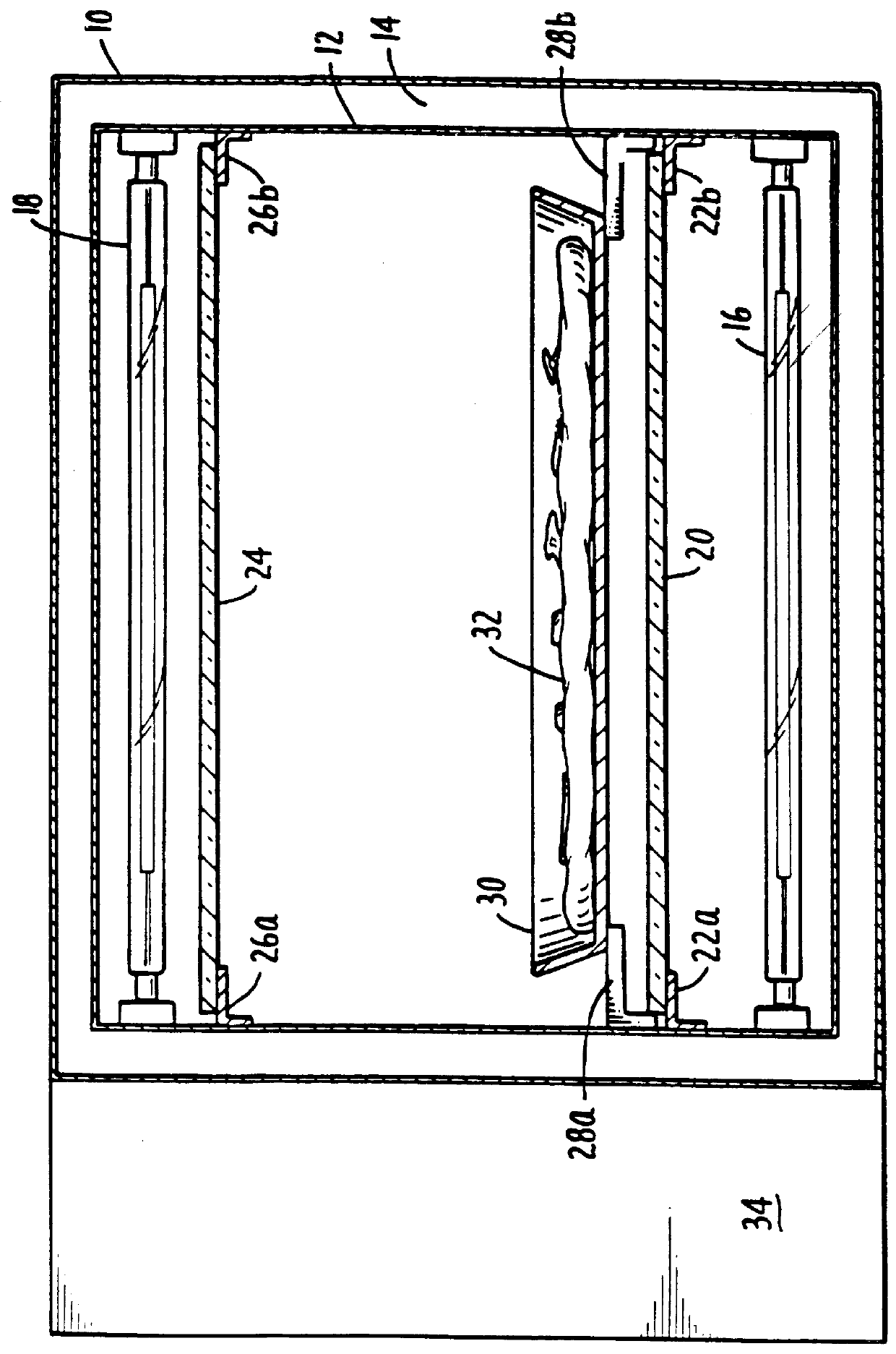
FIG. 1 is a front cross section of the preferred embodiment of the present invention. The oven in FIG. 1 includes an outer enclosure 10. The enclosure has an inner wall 12 coupled to the outer wall 10. Ordinarily, an insulating layer 14 is formed between the outer enclosure 10 and the inner wall 12. Because of the inherent speed of the cooking cycle, the insulating layer 14 may be a layer of air.

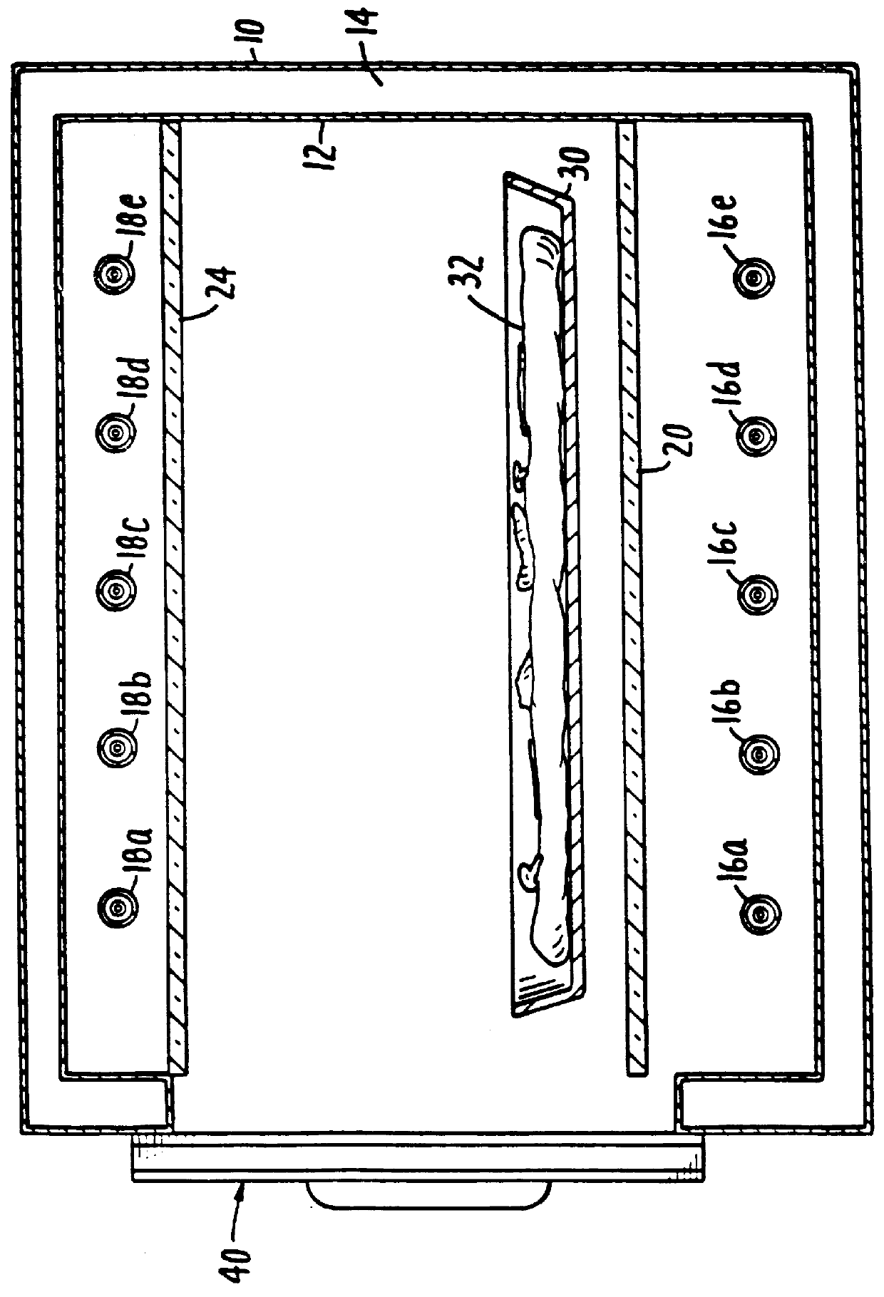
The energy for cooking is supplied by the lower radiation heating lamps 16 and the upper radiation heating lamps 18. These lamps are generally any of the quartz body, tungsten-halogen lamps commercially available, e.g., 1.5 KW 208 V quartz-halogen lamps. The oven according to the preferred embodiment utilizes ten such lamps and cooks with an average of 10% of the energy in the visible light portion of the spectrum, which is significant. The inner surface of the inner wall 12 is preferably a highly polished, poorly absorptive surface, so that it appears to be very reflective to the wide spect...


PUM


Abstract

An oven using one or more quartz tungsten light bulbs capable of producing 1.5 kW of radiant energy of which a significant portion is light energy in the 0.4 to 0.7 mu m wavelength range impinges high intensity visible light wave radiation directly onto a food item. Light sources can be positioned above and below the food item and the inner walls of the oven are preferably highly reflective to reflect light energy onto the food. The intensity of the visible light source is automatically controllable and can be varied throughout the cooking cycle.

Description

FIELD OF THE INVENTIONThis invention relates to the field of cooking apparatus. More particularly, this invention relates to baking and cooking processes that are substantially faster than such processes in conventional ovens, and offer sensory improvements in quality for many foodstuffs.BACKGROUND OF THE INVENTIONOvens for cooking food have been known and used for thousands of years. Basically, oven types can be categorized in four different forms. The simplest and probably the oldest cooking resulted when man put some vegetable or grain products on a hot rock next to a fire, and cooked them essentially by the heat transfer method of conduction. With a little more refinement, an enclosure surrounding the heating element entrapped the heated air giving rise to cooking by convective heat transfer. This was the prototype for the modern gas or electric oven. In the past century, radiant energy from infra-red radiation sources has been used to heat and cook foodstuffs directly. Within t...

Claims


Application Information

Patent Timeline
IPC IPC(8): H05B3/68H05B6/80A47J27/62A47J37/06F24C7/06F24C7/08G01L1/14G05D1/08H05B3/00
CPCA47J27/62A47J37/0635F24C7/06H05B3/0076G01L1/144G05D1/0816F24C7/087A47J36/32
Inventor WESTERBERG, EUGENE R.BEAVER, II, ROBERT I.
Owner GENERAL ELECTRIC CO
Why Eureka
Try Eureka