Offset head-spindle for chemical mechanical polishing

Active Publication Date: 2020-05-21
APPLIED MATERIALS INC
View PDF0 Cites 0 Cited by
  • Summary
  • Abstract
  • Description
  • Claims
  • Application Information

AI Technical Summary

Benefits of technology

The patent explains a technique called offset distance that helps improve the polishing process for electronic devices. By shifting the position of a carrier head, the surface area can be increased, resulting in more uniform polishing. This technique effectively allows the carrier head to rotate around its axis, which allows for more surface coverage.

Problems solved by technology

One drawback of CMP systems in the current art is a small variation in the head sweep, which causes the polishing surface to go over the same area multiple times and results in the non-uniform polishing of the wafers.

Method used


Image

  • Offset head-spindle for chemical mechanical polishing
  • Offset head-spindle for chemical mechanical polishing
  • Offset head-spindle for chemical mechanical polishing

Examples


Embodiment Construction

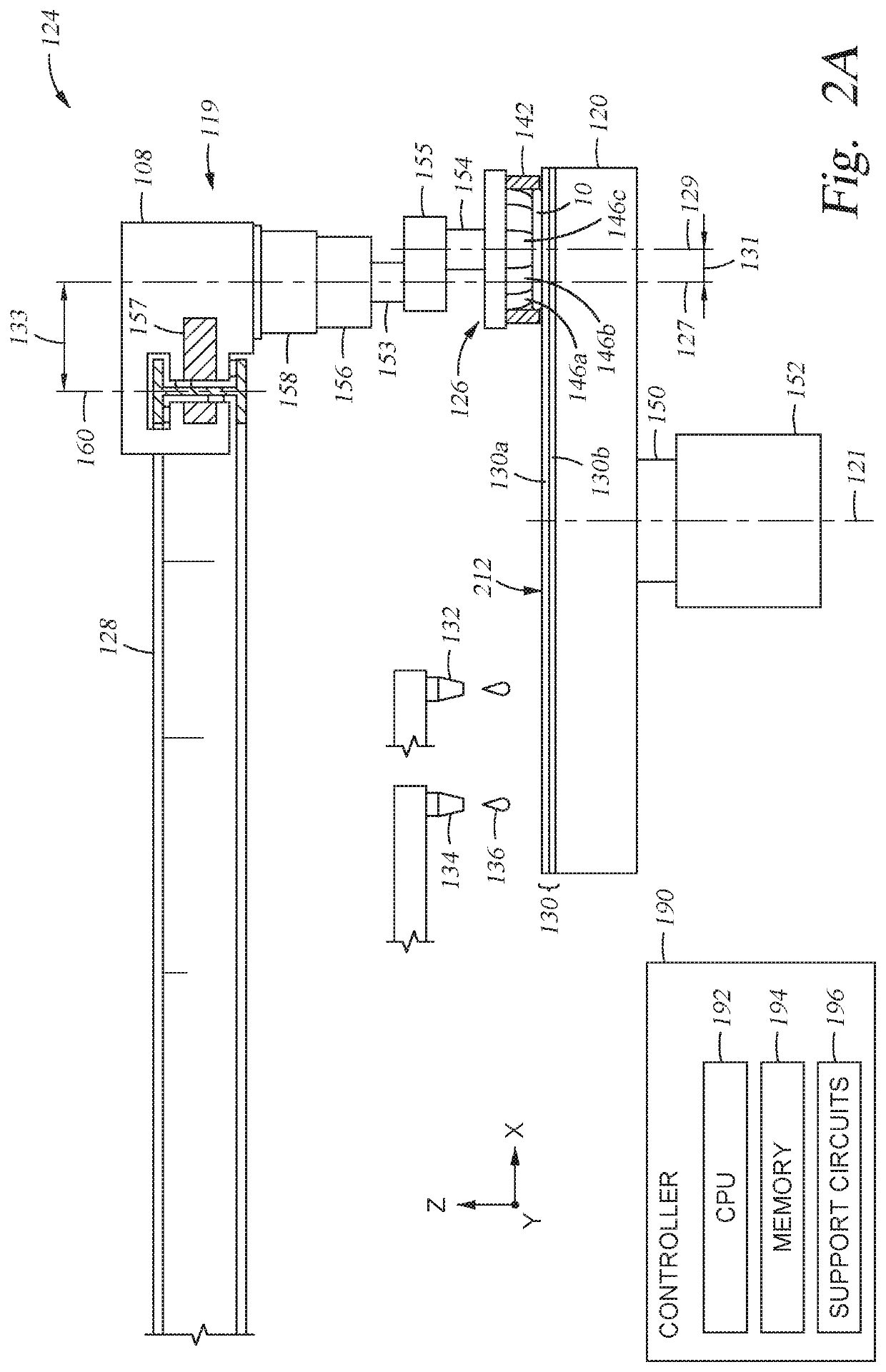
[0023]Embodiments of the disclosure provided herein include a polishing method and apparatus used to provide a uniform polishing of a surface of a substrate. In some embodiments, a carrier head is shifted relative to the attachment point of the support structure. The rotation of the carrier head around the offset attachment point results in more of the polishing surface being accessed due to a larger surface area of the pad being accessed, and reduces the amount of frictional force provided to a carrier head motor attached to a carriage that supports carrier head during operation. Embodiments of the disclosure provided herein may be especially useful for, but are not limited to, improving the polishing performance of a chemical mechanical polishing system.

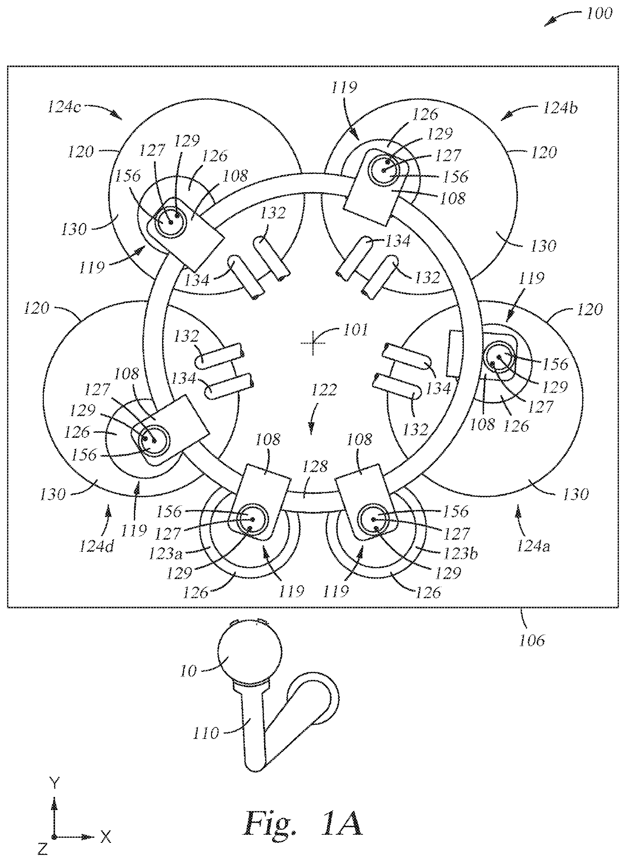
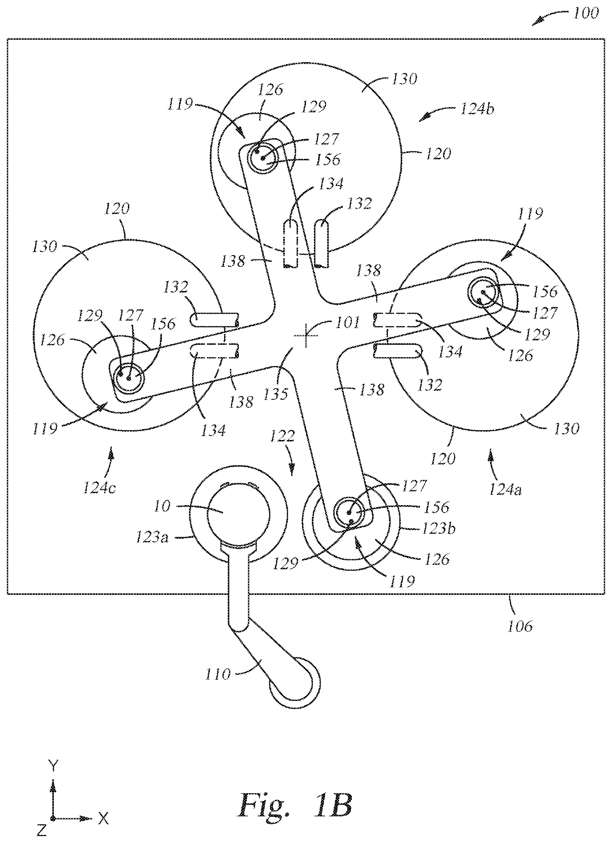
[0024]FIG. 1A is a plan view of a polishing system 100, which contains an overhead track 128, and several carrier head assemblies 119, which carry the substrates 10 around the system during processing. The geometry of the polishing...


PUM


Abstract

A polishing system is provided, including a carrier with an offset distance. The offset distance allows a shifted carrier head to cover more surface area of the polishing surface. The offset distance effectively provides an additional rotation of the carrier head about the axis, which allows for a greater area traversed on the polishing surface, improving chemical mechanical polishing uniformity on the substrate.

Description

CROSS-REFERENCE TO RELATED APPLICATIONS[0001]This application claims the benefit of U.S. Provisional Patent Application No. 62 / 770,716, filed Nov. 21, 2018, which is hereby incorporated by reference in its entirety.BACKGROUNDField[0002]The present invention relates generally to a method and an apparatus used to polish a substrate. More specifically, this invention relates to a chemical mechanical polishing system.Description of the Related Art[0003]An integrated circuit is typically formed on a substrate by the sequential deposition of conductive, semiconductive, or insulative layers on a silicon wafer. One fabrication step involves depositing a filler layer over a non-planar surface and planarizing the filler layer. For certain applications, the filler layer is planarized until the top surface of a patterned layer is exposed. A conductive filler layer, for example, can be deposited on a patterned insulative layer to fill the trenches or holes in the insulative layer. After planariz...

Claims


Application Information

Patent Timeline
IPC IPC(8): B24B37/30
CPCB24B37/30B24B37/105B24B37/10B24B37/102B24B37/07
Inventor ZUNIGA, STEVEN M.GURUSAMY, JAYKIM, BUM JICKLOI, DANIELLE
Owner APPLIED MATERIALS INC
Why Eureka
Try Eureka