Removable optoelectronic module
- Summary
- Abstract
- Description
- Claims
- Application Information
AI Technical Summary
Benefits of technology
Problems solved by technology
Method used
Image
Examples
Embodiment Construction
Referring to the drawing, and particularly to FIG. 1, an enlarged perspective view of an optoelectronic transceiver module 10 in accordance with the present invention is depicted. The module 10 has a main housing 12 which generally has the shape of an oblong box. The main housing 12 has a generally rectangular top 14 with a first end 16 and an opposite second end 18 extending perpendicularly from the top. Attached to the first end 16 of the main housing 12 is a transceiver connector 20 for receiving fiber optic plugs.
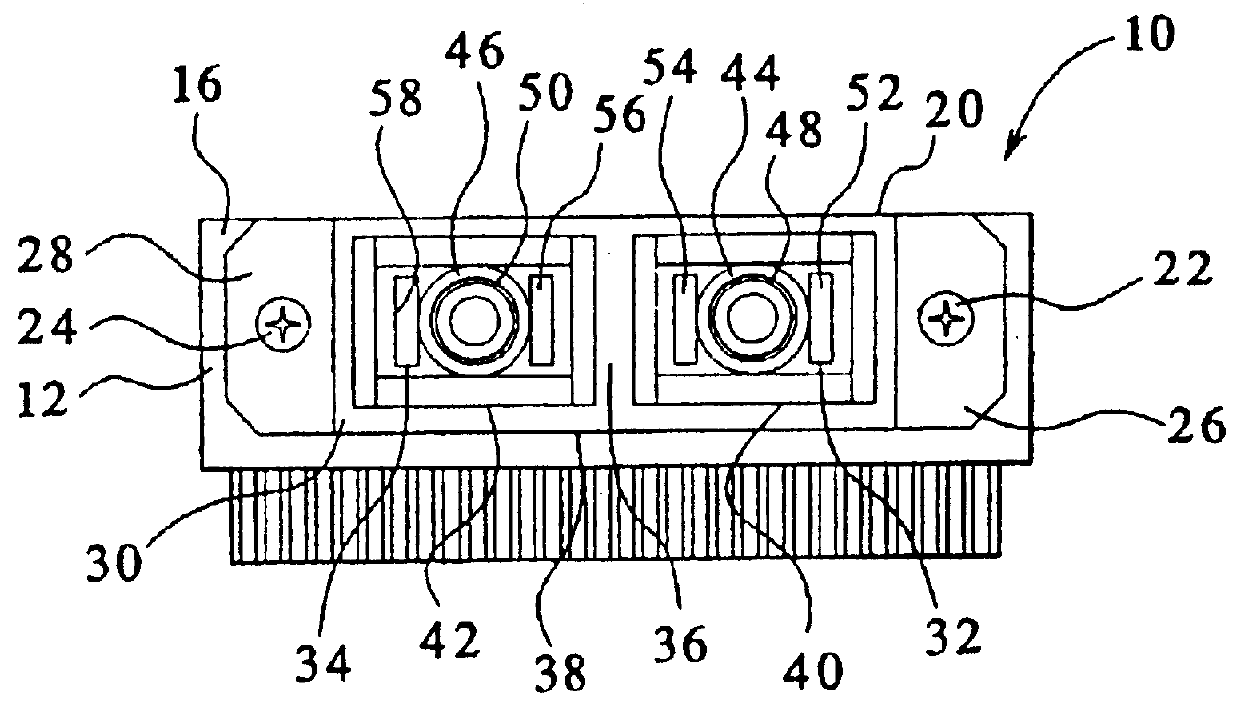
Turning to FIG. 2, a front view of the optoelectronic transceiver module 10 is depicted. The transceiver connector 20 is attached to the first end 16 of the main housing 12 by two screws 22,24. The two screws 22,24 extend through the transceiver connector's mounting ears 26,28 and into the main housing 12. Extending perpendicularly from the mounting ears 26,28 is a generally rectangularly shaped connector shell 30. The connector shell 30 provides two receptacles 32,34 f...
PUM
 Abstract
Description
Claims
Application Information
 - R&D
- Intellectual Property
- Life Sciences
- Materials
- Tech Scout
- Unparalleled Data Quality
- Higher Quality Content
- 60% Fewer Hallucinations
Browse by: Latest US Patents, China's latest patents, Technical Efficacy Thesaurus, Application Domain, Technology Topic, Popular Technical Reports.
© 2025 PatSnap. All rights reserved.Legal|Privacy policy|Modern Slavery Act Transparency Statement|Sitemap|About US| Contact US: help@patsnap.com


