Glass bulb for a cathode ray and a method of producing the same

a glass bulb and cathode ray technology, applied in the direction of cathode ray tubes/electron beam tubes, electric discharge tubes, electrical apparatus, etc., can solve the problems of instantaneous release of temporal distortion, cracks in glass, and shrinkage of glass inside, so as to prevent or delay cracks, reduce the difference of brightness, and light weight

Inactive Publication Date: 2000-08-29
ASAHI GLASS CO LTD
View PDF7 Cites 19 Cited by
  • Summary
  • Abstract
  • Description
  • Claims
  • Application Information

AI Technical Summary

Benefits of technology

According to the glass panel portion of the present invention, the difference of thickness between the central portion and the peripheral portion of the face portion is small; the face portion has a uniform wall thickness; the glass is strengthened by the compressive stress layers formed inner and outer surfaces of the face portion, and the face portion has a flat surface while the wall thickness is thin. Namely, at least the face portion of the glass panel portion has the compressive layers each having a stress value and a thickness sufficient to preventing or delaying the development of a crack, wherein the compressive layers are formed by physically strengthening method.
With use of the glass panel, there is obtainable a glass bulb for a cathode ray tube which has a light weight, minimizes the difference of brightness between the central portion and a

Problems solved by technology

Accordingly, if a mechanical shock is applied to the glass bulb and a crack or breakage is resulted in a local portion, the local crack or the local breakage is instantaneously developed to release a stored strain energy; thus, implosion is resulted.
However, the inside of the glass is in a state having a sufficient fluidity and expansion, and a temporal distortion is instantaneously released by the fluidity.
When the glass bulb is further cooled, the inside of the glass tends to shrink.
However, the movement of shrinkage is limited by the solidified surface layer.
In the conventional glass bulb for a cathode ray tube, when the radius of curvature of the glass panel is made small in order to increase the strength of the panel to a shock, visibility becomes poor and pictures are unclear.
However, there arises a problem that when the face portion is made flat, it becomes weak to a mechanical shock.
Further, when the reinforcing band is attached to the glass panel, an uneven fastening force is applied to the skirt portion which is joined to the peripheral edge of the face portion, and stable and highly reliable implosion-proof properties can not be obtained with the result that the purpose of reinforcing of the face portion can not be sufficiently achieved.
On the other hand, when the entirety of the face portion is made thick to obtain suff

Method used


Image

  • Glass bulb for a cathode ray and a method of producing the same
  • Glass bulb for a cathode ray and a method of producing the same
  • Glass bulb for a cathode ray and a method of producing the same

Examples


Embodiment Construction

Preferred embodiments of the present invention will be described in more detail with reference to the drawings.

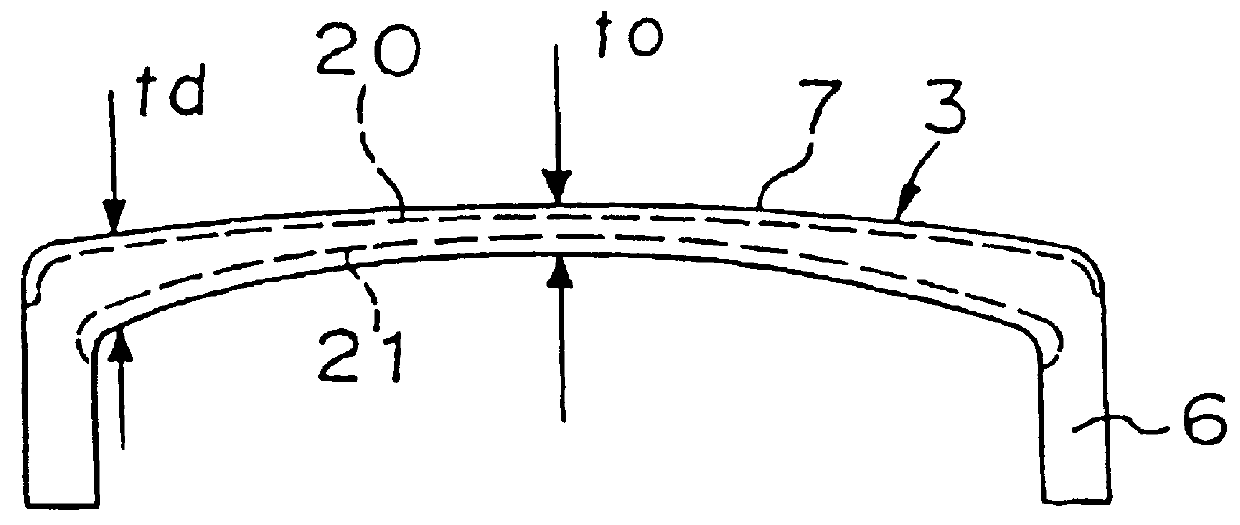
FIG. 1 is a cross-sectional view of an embodiment of the glass panel 3 for a glass bulb for a cathode ray tube. The glass panel is formed so as to be 1.0.ltoreq.t.sub.d / t.sub.o .ltoreq.1.2 where t is the wall thickness of the central portion of a face portion 7 and t.sub.d is the wall thickness of a peripheral portion of the face portion 7. Namely, the glass panel has a uniform wall thickness by determining the ratio of the thicknesses of the central portion to the thickness of the peripheral portion of the face portion to be 1 or a new value. Thus, the light transmittance and the absorptivity coefficient of glass are substantially uniform in the entirety of the face portion, and the difference of brightness between the central portion and the peripheral portion is small, whereby the picture surface can be easily watched.

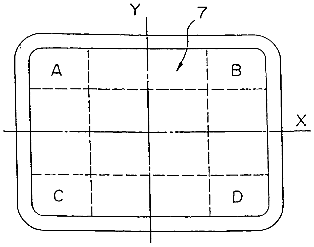
FIG. 2 is a plane view of the face portion 7 of the ...


PUM


Abstract

A glass panel 3 for a glass tube for a cathode ray tube has a flat panel face portion 7 and a reduced thickness while maintaining a sufficient strength without increasing a difference of brightness, and with less shrinking deformation due to the cooling and solidification of the glass panel. Compressive stress layers 20, 21 having a thickness of to/10 or more are formed in outer and inner surfaces of the face portion 7 of the glass panel 3 respectively. The relation to the wall thickness td of the central portion of the face portion to the wall thickness to of a portion near an edge portion on a diagonal line is 1.0</=td/to</=1.2. Compressive stress layers 22, 23 are formed in outer and inner surfaces of a skirt portion 6 wherein the compressive stress value of the face portion 7 is larger than the compressive stress value of the skirt portion, and the compressive stress value of the outer surface 20 of the face portion is larger than that of the inner surface 21.

Description

BACKGROUND OF THE INVENTIONFIELD OF THE INVENTIONThe present invention relates to a glass bulb for a cathode ray tube (a Braun tube) used for TVs and a method of producing the same. More particularly, the present invention concerns the structure of a glass panel constituting the display surface of the glass bulb and method of producing the glass panel.DISCUSSION OF BACKGROUNDFIG. 3 shows the construction of a cathode ray tube used for a TV or the like. The cathode ray tube 1 comprises a glass bulb 2 which is basically constituted by a glass panel portion 3 constituting a picture displaying surface, a funnel portion 4 in a funnel-like form which is airtightly joined to the glass panel portion 3 and a neck portion 5 in which an electron gun 17 is installed. The glass panel 3 comprises a substantially rectangular face portion 7 for constituting a picture displaying surface and a skirt portion 6 extending from the circumferential portion of the face portion 7 in substantially perpendicu...

Claims


Application Information

Patent Timeline
IPC IPC(8): H01J29/86H01J29/87
CPCH01J29/861H01J29/87H01J2229/8616H01J2229/862
Inventor SUGAWARA, TSUNEHIKOMORIHIRO, NAOKIIKEZAWA, TOSHIKAZUMURAKAMI, TOSHIHIDEKOBAYASHI, YUSUKE
Owner ASAHI GLASS CO LTD
Why Eureka
Try Eureka