Method and apparatus for containing and suppressing explosive detonations

a technology of explosive detonation and method, applied in the direction of lighting and heating apparatus, combustion types, manufacturing tools, etc., can solve the problems of large space occupation, substantial danger to equipment and personnel, and uncontrolled use of explosives, so as to dampen and suppress the shock and noise of each detonation

Inactive Publication Date: 2000-10-17
ABC NACO +2
View PDF22 Cites 32 Cited by
  • Summary
  • Abstract
  • Description
  • Claims
  • Application Information

AI Technical Summary

Benefits of technology

is to provide a means of quickly removing and treating the gaseous explosion by-products by passing them through a scrubber system, so that operating personnel can re-enter the chamber immediately while the scrubber continues to process the products of the previous explosion as a new work piece and explosive charge are being readied. Also, it is an object of the scrubber system to further dampen and suppress shock and noise from each detonation by virtue of the extended travel path of the explosion products as they pass through the scrubber.

Problems solved by technology

In addition, the uncontrolled use of explosives required great amounts of space, posed substantial danger to equipment and personnel, and had the undesirable effect of demolishing the ignition leads, the work piece support surface, and everything else within the immediate vicinity of the explosion.

Method used


Image

  • Method and apparatus for containing and suppressing explosive detonations
  • Method and apparatus for containing and suppressing explosive detonations
  • Method and apparatus for containing and suppressing explosive detonations

Examples


Embodiment Construction

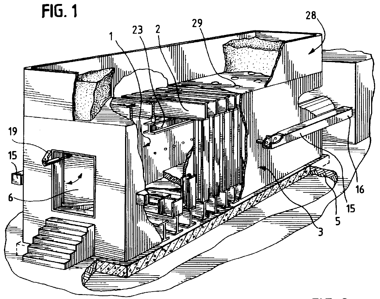
Turning to the drawings, FIG. 1 is a sectional perspective of the improved explosion chamber of the present invention. The chamber comprises an inner casing 1 having a ceiling, floor, side walls and ends, being fabricated of sheet steel using conventional welding techniques. Surrounding the inner casing 1 are a plurality of spaced circumstantial flanges or ribs 2 over which a welded sheet steel outer casing 3 is constructed so that the ribs 2 cause the outer casing 3 to be spaced from the inner casing 1 and leaving a gap which is then filled with a granular shock-damping material .Iadd.4.Iaddend.. In the preferred embodiment, the inner and outer metal casings are constructed of three-quarter inch thick sheet steel separated by circumferential steel I-beam ribs 2 spaced every two feet. All seams are continuous-welded. According to the invention, the space between the inner and outer casing 3 is filled with a firm, granular shock-absorbing material, preferably silica sand.

The explosio...


PUM

PropertyMeasurementUnit
thickaaaaaaaaaa
thickaaaaaaaaaa
depthaaaaaaaaaa

Abstract

[A method and apparatus for enclosing, controlling and suppressing the detonation of explosives in an explosion chamber is disclosed. The device comprises an elongate double-walled steel explosion chamber anchored to a concrete foundation, and having a double-walled access door for charging new workpieces, and a double-walled vent door for discharging the products of the explosion. The double walls of the chamber, access door and vent door are filled with granular shock damping material such as silica sand, and the floor of the chamber is covered with granular shock-damping bed such as pea gravel. Along the outside of the chamber are steel manifolds from which a linear array of vent pipes penetrates the double walls of the chamber, with each pipe terminating in a hardened steel orifice through which the explosion combustion products pass. Within the chamber, plastic polymer film bags containing water are suspended from steel wires over the explosive material, and at each end of the chamber.] A method and apparatus for containing and suppressing the detonation of explosives utilizing a sealable double-walled chamber having a floor, an access door and a vent door. The chamber walls are filled, and the floor is covered, with granular shock-damping material. Orificed vent pipes penetrate the chamber walls to vent explosion products into one or more exhaust manifolds. Water-filled bags are positioned around the explosive to absorb energy from the detonation.

Description

FIELD OF THE INVENTIONThis invention relates to a method and apparatus for containing, controlling and suppressing the detonation of explosives, particularly for the explosion working of metals, and for the disposal of unwanted explosive and toxic materials.BACKGROUND OF THE INVENTIONExplosives have many useful industrial applications including surface hardening of austenitic manganese alloy steels, surface deposition coating, welding of metallic components, compression molding of components from powders and granular media, and disposal of unwanted explosive or toxic materials.The prior art reflects many attempts to contain the explosion process for the suppression of noise, shock and noxious polluting explosion products.Hampel U.S. Pat. No. 5,419,862 discloses a large explosion chamber in which an explosive work piece is introduced in through an air lock into a vacuum chamber where it is detonated, and after detonation the explosion products are allowed to escape into the atmospher...

Claims


Application Information

Patent Timeline
Patent Type & Authority Patents(United States)
IPC IPC(8): F23G7/00A62D3/00B21D26/02B21D26/08B21J5/04B30B5/00C21D1/06F23N5/24F42B3/00F42B33/00F42B33/06F42D5/04F42D5/045
CPCF42D5/045F42B33/06
Inventor DONOVAN, JOHN L.
Owner ABC NACO
Why Eureka
Try Eureka