Single phase motor with positive torque parking positions

a single-phase, positive technology, applied in the direction of instruments, lighting and heating apparatus, magnetic circuit shape/form/construction, etc., can solve the problems of difficult starting of the motor, more difficult to reverse the rotational direction of the rotor, and difficulty in starting the motor

Inactive Publication Date: 2002-03-12
GENERAL ELECTRIC CO
View PDF69 Cites 73 Cited by
  • Summary
  • Abstract
  • Description
  • Claims
  • Application Information

AI Technical Summary

Benefits of technology

Among the several objects of this invention may be noted the provision of an improved motor which provides a positive torque parking position; the provision of such a motor which is particularly well suited for use in a horizontal axis washing machine; and the provision of such a motor system which is economically feasible and commercially practical.

Problems solved by technology

As is known in the art, single phase brushless motors typically have starting problems.
In a single phase motor, the rotor's parking positions can coincide with positions of zero electromagnetic torque production which makes it difficult to start the motor.
This problem can also make it more difficult to reverse the rotor's direction of rotation.
One approach to overcome this problem is to provide a starting winding which disadvantageously increases the cost and complexity of the motor.
Although several motor configurations are known for parking a motor's rotor in a particular position, these motor configurations increase the cost of the motor and / or fail to provide parking positions with sufficient starting torque, especially for low torque motors such as single phase electronically commutated motors.

Method used


Image

  • Single phase motor with positive torque parking positions
  • Single phase motor with positive torque parking positions
  • Single phase motor with positive torque parking positions

Examples


Embodiment Construction

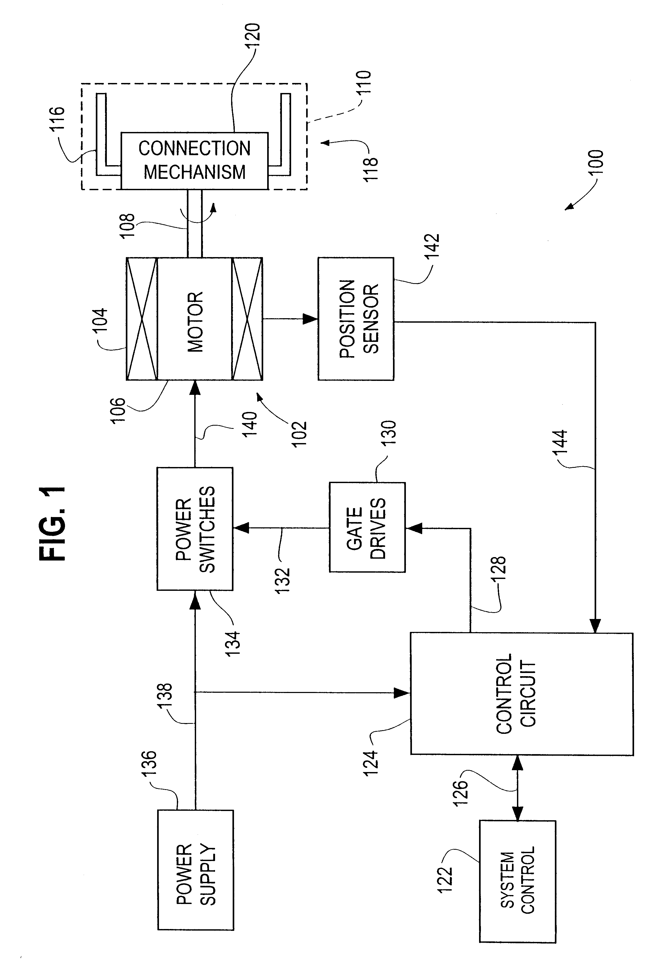
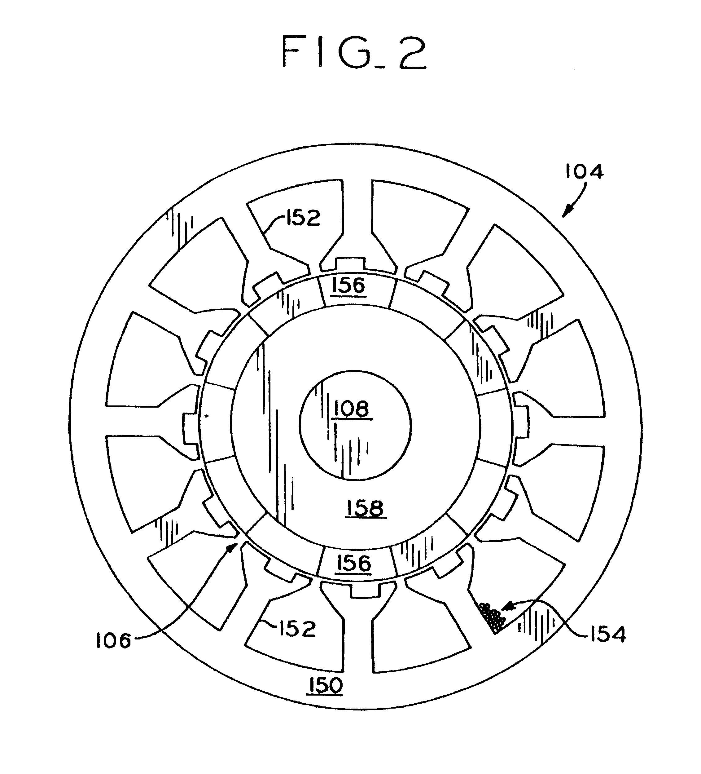
Referring now to the drawings, FIG. 1 shows a motor system 100 according to a preferred embodiment of the present invention. The system 100 includes a motor, generally designated 102, having a stationary assembly, or stator, 104 and a rotatable assembly, or rotor, 106 in magnetic coupling relation to the stator 104. In the embodiment described herein, the motor 102 is a single phase, permanent magnet motor. It is to be understood, however, that aspects of the present invention may be applied to electronically controllable motors or dynamoelectric machines such as single phase permanent magnet motors, external rotor motors (i.e., inside out motors), single and variable speed motors, selectable speed motors having a plurality of speeds, brushless dc motors and electronically commutated motors. Such motors may also provide one or more finite, discrete rotor speeds selected by an electrical switch or other control circuit.

In a preferred embodiment of the invention, a motor shaft 108 mec...


PUM


Abstract

A motor with positive torque parking positions. The motor includes a rotor which is rotatable about an axis of rotation and a stator in magnetic coupling relation with the rotor. The stator includes a plurality of teeth each having a radially extending shaft and an axially extending face. The faces of the stator teeth define an aperture for receiving the rotor and the faces of the stator teeth and the rotor define a air gap therebetween. Each stator tooth has a notch in its face that is approximately at least as wide as the shaft of the stator tooth so that the stator has a magnetic configuration relative to the rotor for parking the rotor in a rest position corresponding to a positive torque starting position. The motor also includes a winding on the shafts of the stator teeth and a control circuit for controlling current in the winding whereby an electromagnetic field is produced for rotating the rotor at a desired speed or torque during the operation of the motor.

Description

BACKGROUND OF THE INVENTIONThis invention relates generally to motors and stationary assemblies therefor and, particularly, to an improved stationary assembly for providing positive torque parking positions in a single phase electronically commutated motor for use in a horizontal axis washing machine.In general, a motor such as an electronically commutated or brushless motor has permanent magnets mounted on its rotor. The stator of such a motor has a plurality of teeth and wire-wound coils on the teeth which, when energized with current, interact with the permanent magnet rotor to produce positive or negative torque, depending on the direction of the current with respect to the polarity of the magnets. The polarity of the magnets relative to the stator winding alternates when the rotor moves unidirectionally. Thus, it is necessary to alternate the direction of the stator current in synchronism to maintain a constant direction of torque. An electronic inverter bridge typically contro...

Claims


Application Information

Patent Timeline
Patent Type & Authority Patents(United States)
IPC IPC(8): F23N3/08F23N1/06F23N1/00F23N3/00G05D13/30G05D13/00H02K29/06H02M5/458H02P6/08H02P25/02H02K29/03H02K1/14H02K3/18H02M5/00H02P6/00H02K29/08H02P25/04H02P6/20F23N5/18
CPCF23N1/062F23N3/082F23N5/18F23N2225/04F23N2225/06F23N2233/04G05D13/30H02K1/146H02K1/148H02K3/18H02K29/03H02K29/08H02K2201/06H02M5/458H02P6/08H02P6/085H02P6/20H02P25/04H02P6/26
Inventor STEPHENS, CHARLES M.SOONG, WEN LIANG
Owner GENERAL ELECTRIC CO
Why Eureka
Try Eureka