Two-flap closure

a closure and two-flap technology, applied in the field of containers, can solve the problems of inconvenient size restriction, tendency of the closure to take an out-of-round or oval set, non-symmetry of the cap, etc., and achieve the effect of reducing quality-related problems and high total retention for

Inactive Publication Date: 2002-04-09
WEATHERCHEM
View PDF13 Cites 83 Cited by
  • Summary
  • Abstract
  • Description
  • Claims
  • Application Information

AI Technical Summary

Benefits of technology

The invention provides an injection-molded plastic shake-and-spoon closure which has a proportionately large, unrestricted spoon aperture, and which reduces quality-related problems found in prior art products. The closure includes novel catch means associated with the aperture cover flaps that produce consistent retention and release action and is relatively tolerant of dimensional variations due to thermal shrinkage and any tendency towards ovality of the molded parts. In accordance with the invention, the flaps are formed with a wall thickness substantially equal to the nominal wall thickness of the remainder of the closure and are devoid of heavy stiffening ribs. The non-rigid flap structure permits it to be opened in a peeling motion so that the forces of individual catches are encountered progressively as the flap is opened, whereby the high total retention force need not be overcome at once. The disclosed closures include a wide internal sealing ledge which ensures that the closure will positively seal the mouth of a container, regardless of any expected degree of ovality. A land area between the spoon and shake apertures has the same elevation as the sealing ledge. This land area can provide support for intermediate areas of a paper seal which can be particularly important when the seal is stamped into the closure by automatic high speed equipment.

Problems solved by technology

This restricted size can be inconvenient in certain instances, such as in commercial establishments and institutions where relatively large spoons are used by a cook.
A more subtle problem with shake-and-spoon closures faceed by the manufacturer is the tendency of the closure to take an out-of-round or oval set when released from the mold.
The cause of this ovality is the non-symmetry of the cap to an absence of plastic stock on one side of the closure where the spoon aperture exists and substantial stock on the other side exits to surround the small shake apertures.
Because of the non-symmetry of the plastic mass, thermal shrinkage is uneven.
Resultant ovality can detract from the appearance of the container and closure, cause problems in automatic container capping machines, make it difficult to achieve a good seal with the mouth of the container, and increase the difficulties of providing reliable retention of the flaps in the closed positions.
In general, each of these problems tends to be aggravated where the size of the spoon aperture is increased at the expense of the cap area allotted to the shake apertures.
This rib can have the disadvantage of obstructing, and thereby lessening, the effective size of the spoon aperture.

Method used


Image

  • Two-flap closure
  • Two-flap closure
  • Two-flap closure

Examples


first embodiment

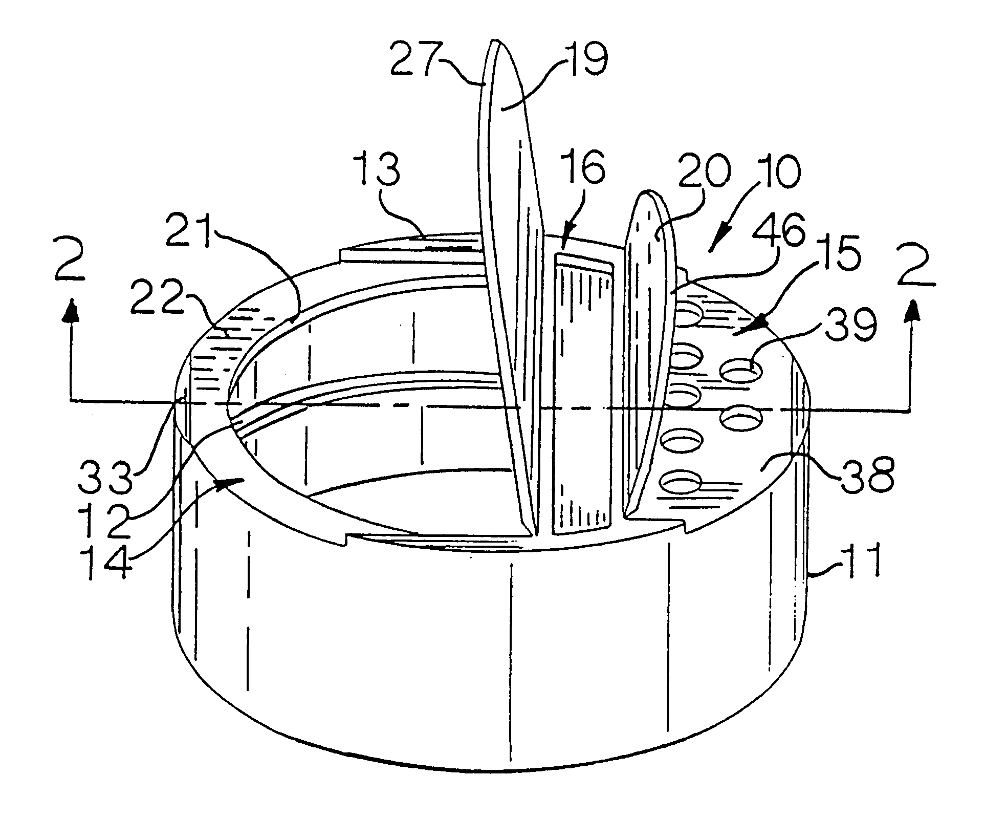
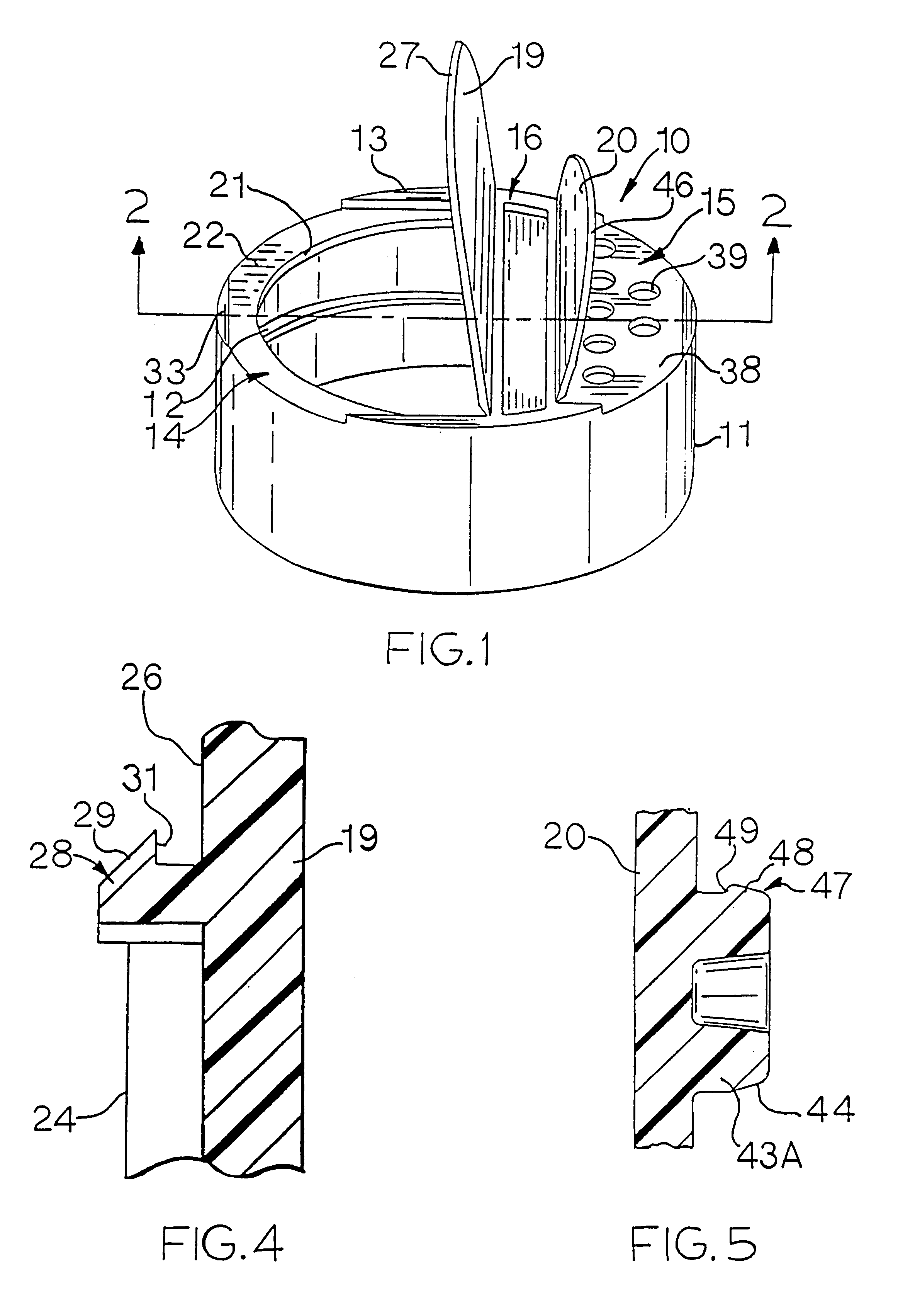
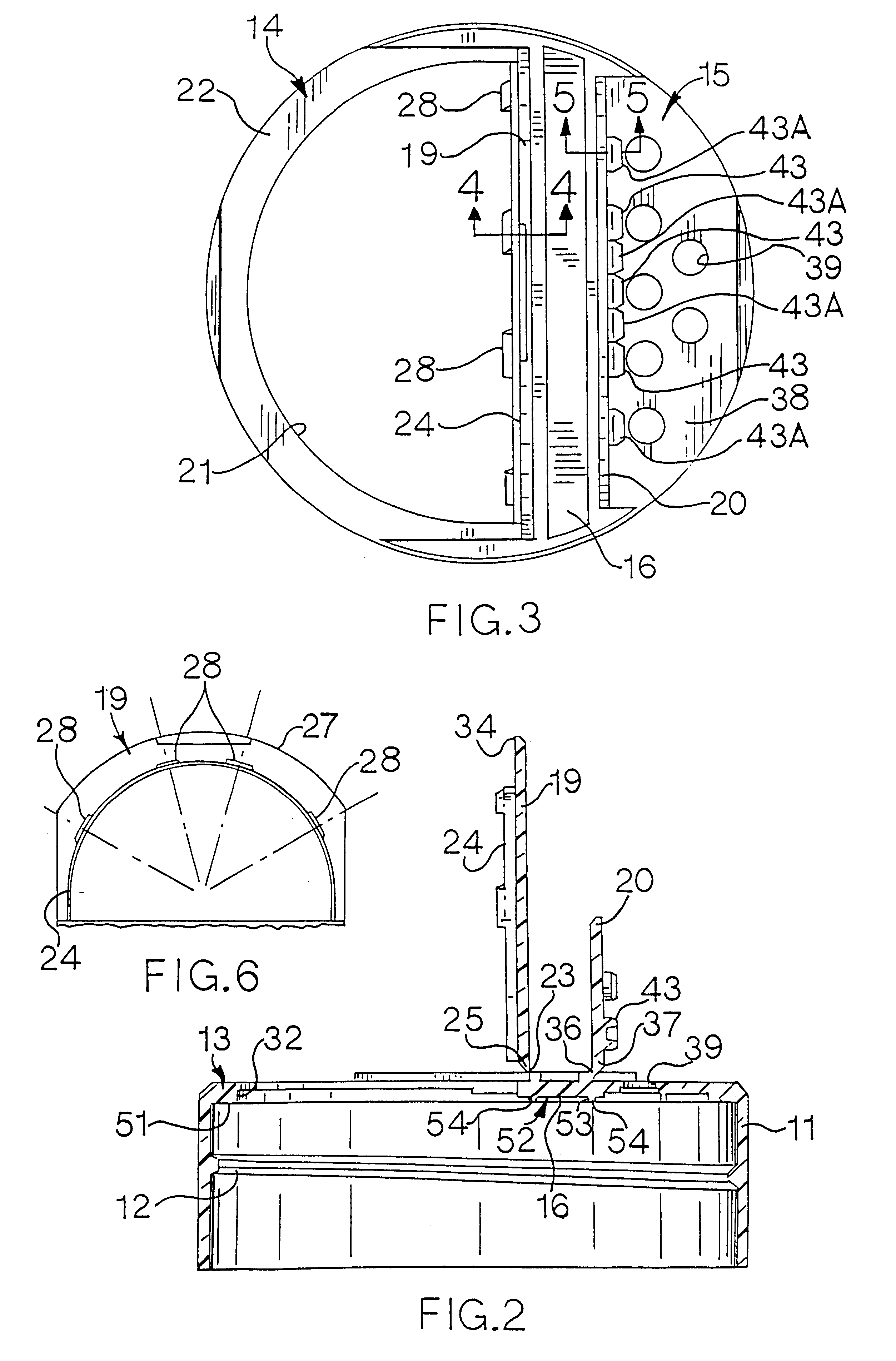
Referring now to the drawings, a two-flap closure or cap 10 constructed in accordance with the invention is shown in FIGS. 1 through 6. The cap or closure 10 is arranged to dispense pourable material in either a spoon or a shake mode from a container (not shown) on which it is mounted. The cap 10 is a unitary injection-molded plastic part, preferably formed of thermoplastic material such as polypropylene. The cap 10 is circular in plan view and includes a cylindrical tubular skirt 11. Screw threads 12 on the interior of the skirt 11 mate with external screw threads on the mouth of a container for the purpose of mounting the cap 10 to the container. An end wall 13, bounded by the skirt 11, is divided into spoon and shake sections 14, 15 by a chordal land area 16. In the illustrated case, the spoon section 14 is considerably larger than the shake section 15, their respective areas roughly representing a division of the end wall 13 by two-thirds for the spoon section and one-third for ...

second embodiment

the invention is illustrated in FIGS. 7 through 13. In this second embodiment, elements of a cap 110 having the same general structure and function as elements of the cap 10 of FIGS. 1 through 6 have been designated by identical numerals. The cap 110 includes means indicated generally at 111 to reduce its tendency to set into an oval configuration upon release from a mold, cooling, and thermal shrinkage. The ovality reducing means 111 comprises reduced wall thickness zones at opposite ends of a chordal land area 16'. As indicated in FIGS. 8 and 12, the land area 16' includes a bar-like rib 113 extending lengthwise of the land 16'. The rib or bar 113 has a relatively heavy cross section in the majority of its length along the land 16'. As seen in FIG. 12, the areas 111 have substantially less thickness, measured vertically, than that of the rib 113.

It is believed that these reduced wall thickness areas or zones 111 form "freeze points" at which relatively quick setting of molten plas...


PUM


Abstract

An injection-molded thermoplastic closure with shake-and-spoon apertures and associated flaps for selectively closing and opening the apertures. The flaps are releasably retained in their closed positions by catch elements which provide retention forces that are relatively insensitive to dimensional and shape variations in the body resulting from the molding process. In one embodiment, the cap has "freeze points" and a gate location that reduce the tendency of the cap to assume an oval condition when cooled from molding temperatures. A wide sealing ledge cooperates with a central support for a liner seal positioned in the cap to seal the mouth of a container.

Description

BACKGROUND OF THE INVENTIONThe invention relates to closures for containers, and more particularly to injection-molded plastic closures with hinged reclosable flaps.PRIOR ARTShake-and-spoon closures for dispensing condiments and the like are generally known in the industry. Typically, such closures take the form of round caps with a pair of semicircular or nearly semicircular flaps. One flap selectively closes and opens a plurality of relatively small apertures for shaking or sifting a pourable product from the container. The other flap selectively closes and opens a relatively large opening in the cap used for spooning product out of the container. Often the cap includes an internally threaded skirt which mates with threads on the mouth of a container for purposes of securing the closure to the container.In certain prior art shake-and-spoon closures of the type described, the spoon opening has been limited to less than half of the mouth opening of the container. This restricted siz...

Claims


Application Information

Patent Timeline
Patent Type & Authority Patents(United States)
IPC IPC(8): B65D47/08
CPCB65D47/0847
Inventor HICKMAN, JOHN R.WEIDMAN, CRAIG C.KRISKA, NICKOLAS J.
Owner WEATHERCHEM
Why Eureka
Try Eureka