Staple and staple applicator for use in skin fixation of catheters

a catheter skin fixation and staple technology, applied in surgical staples, manufacturing tools, veterinary instruments, etc., can solve the problems of affecting the safety of patients, so as to achieve less time-consuming and safer manners

Inactive Publication Date: 2002-08-06
DEAN ALLGEYER M D
View PDF19 Cites 1396 Cited by
  • Summary
  • Abstract
  • Description
  • Claims
  • Application Information

AI Technical Summary

Benefits of technology

The present invention allows fixation of catheters to the skin in a less time-consuming and safer manner than either suturing or the use o...

Problems solved by technology

This procedure includes an attendant risk of needle stick.
To avoid that risk would require the use of a stapler kit, which is far too costly to justify its use for one or two staples.
The use of a stapler would sav...

Method used


Image

  • Staple and staple applicator for use in skin fixation of catheters
  • Staple and staple applicator for use in skin fixation of catheters
  • Staple and staple applicator for use in skin fixation of catheters

Examples


Embodiment Construction

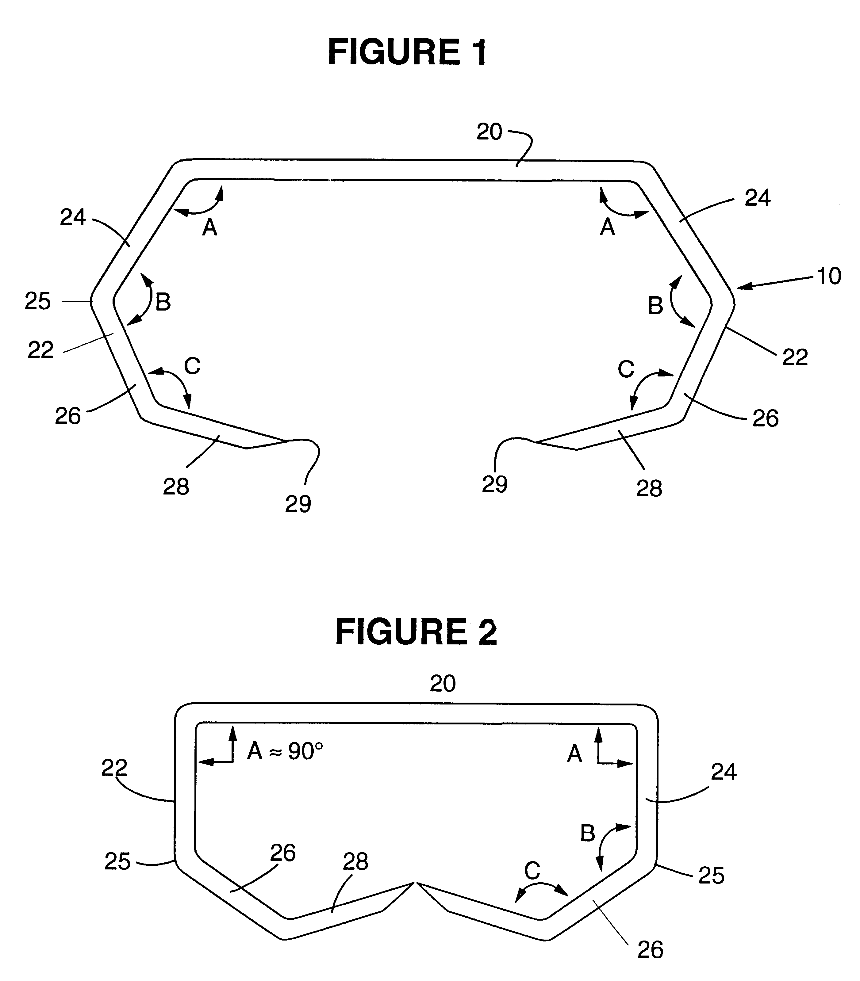
Referring now to FIG. 1, a staple 10 is constructed of stainless steel, titanium, or other similarly deformable material which retains the shape to which it has been deformed. The staple 10 includes a crown portion 20 and opposingly disposed legs 22. In the preferred embodiment, the crown 20 is generally horizontal and connected to legs 22 at each end. Legs 22 are preferably identical and comprised of three segments, 24, 26, and 28, terminating in skin piercing point 29. The three leg segments 24, 26, 28 are offset by three oblique angles A, B, and C, which are approximately 120 degrees each.

FIG. 2 depicts the staple in its closed, deformed configuration. After the staple has been completely closed and the applicator withdrawn, angle A between crown 20 and leg segment 24 should be approximately a 90 degree right angle.

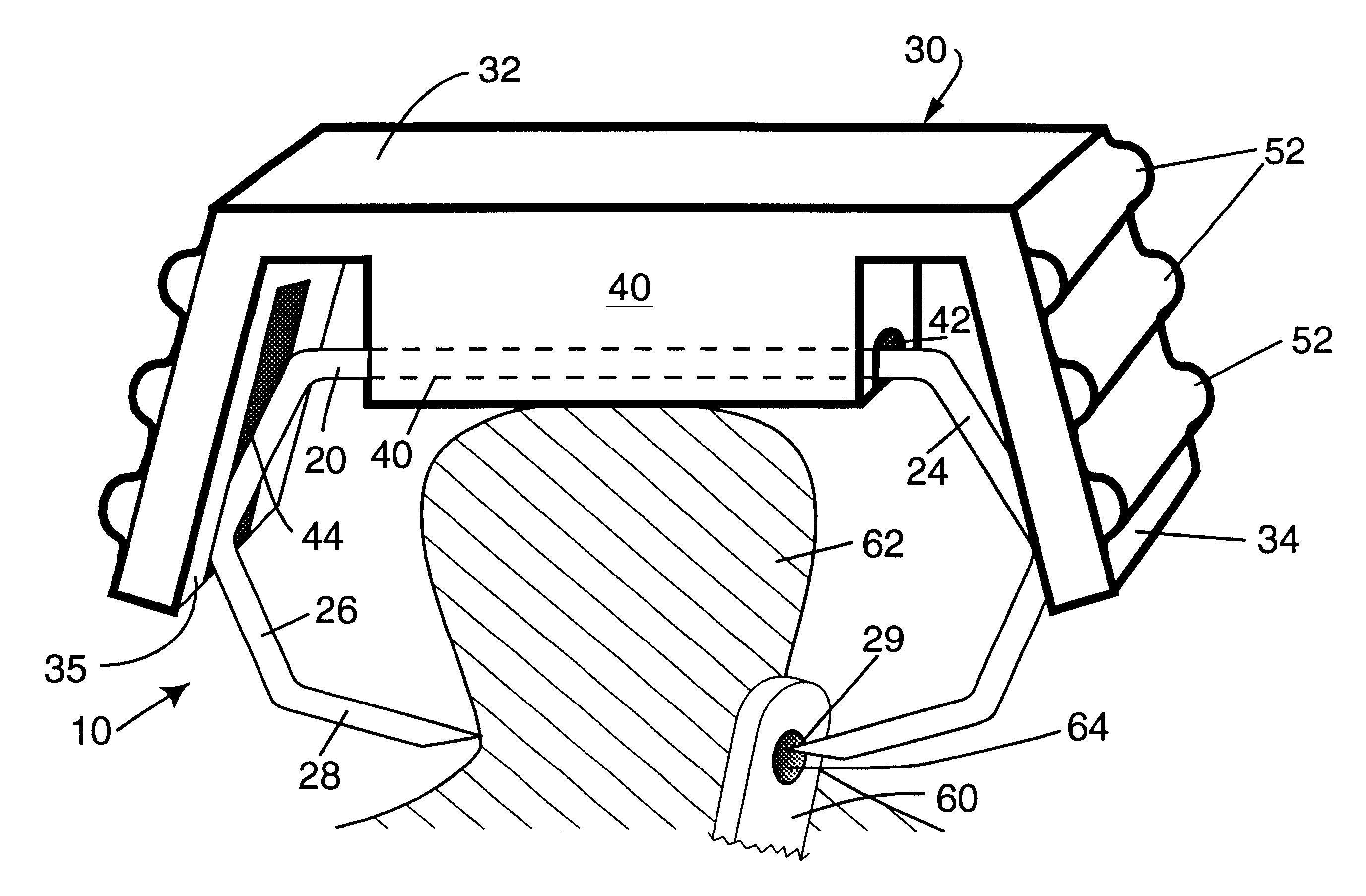
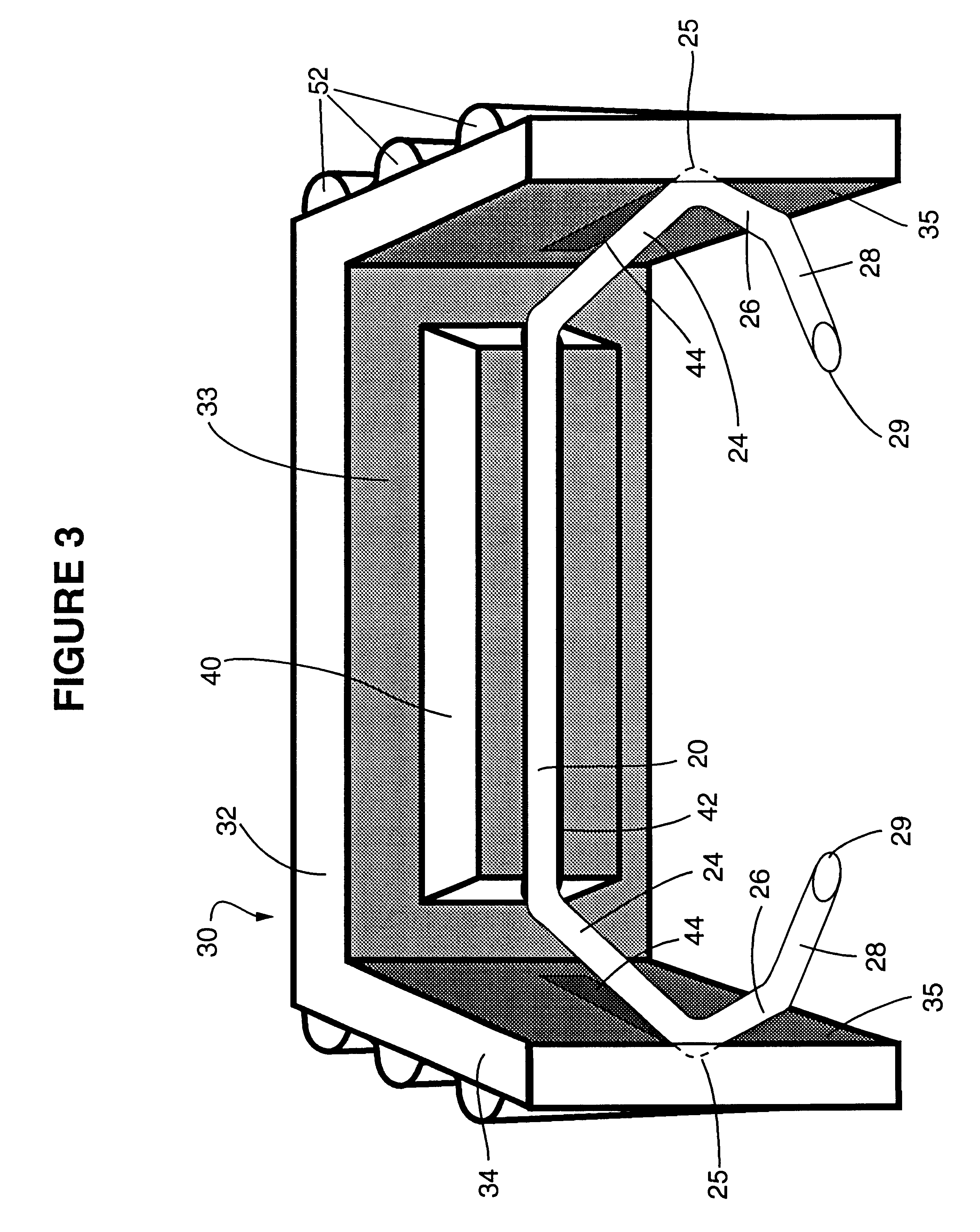
FIGS. 3, 4, and 5 depict an anvilless applicator 30 holding a staple 10 in the open position. The applicator comprises a top or backbone portion 32 and two arms 34. Th...


PUM

PropertyMeasurementUnit
Pressureaaaaaaaaaa
Flexibilityaaaaaaaaaa

Abstract

An inexpensive surgical stapler, such as for use in securing vascular catheters, has a plastic applicator made for use with a single staple. The applicator has a backbone and two identical arms. The inside face of the backbone has a retaining channel that secures the crown portion of the staple against movement. The inside faces of the arms have guidance grooves that direct the movement of the staple as the applicator arms are squeezed with finger pressure. The outside faces of the arms are configured to permit gripping by the operator's fingers. The stapler can be used in lieu of suturing. Other staple and applicator assemblies can include two or more of such assemblies.

Description

BACKGROUND OF THE INVENTIONThis invention relates to medical staples and stapling devices. More particularly, the invention relates to a staple in combination with a flexible, digitally manipulable, anvilless staple applicator that is useful for affixing catheters to the skin and for other medical procedures.Medical stapling devices have been routinely in use for some time. They are designed chiefly to replace the suturing process because of the significantly less time used in stapling. A variety of devices are known. For example, Green, U.S. Pat. No. 5,158,567, describes an anvilless surgical stapler with articulated handles and a slidable staple cartridge mounted in a block at the distal end of the handles. Samuels, U.S. Pat. No. 4,399,810, describes a skin clip applied with an articulating device containing a substantial number of staples. The staples are closed by a lateral pressure from the articulating applier. U.S. Pat. Nos. 4,719,917 and 4,526,174 disclose other medical stap...

Claims


Application Information

Patent Timeline
IPC IPC(8): A61B17/10A61B17/03A61B17/068A61B17/064
CPCA61B17/0644A61B17/0682A61B17/10
Inventor ALLGEYER, DEAN O.
Owner DEAN ALLGEYER M D
Why Eureka
Try Eureka