Method for producing an electrically conductive path on a plastic component

Inactive Publication Date: 2010-06-03
ROBERT BOSCH GMBH
View PDF10 Cites 0 Cited by
  • Summary
  • Abstract
  • Description
  • Claims
  • Application Information

AI Technical Summary

Benefits of technology

[0005]It is an object of the present invention to provide a method for producing electrically

Problems solved by technology

What is disadvantageous in doing this is that these current bars or conductors do not bond

Method used


Image

  • Method for producing an electrically conductive path on a plastic component
  • Method for producing an electrically conductive path on a plastic component
  • Method for producing an electrically conductive path on a plastic component

Examples


Example

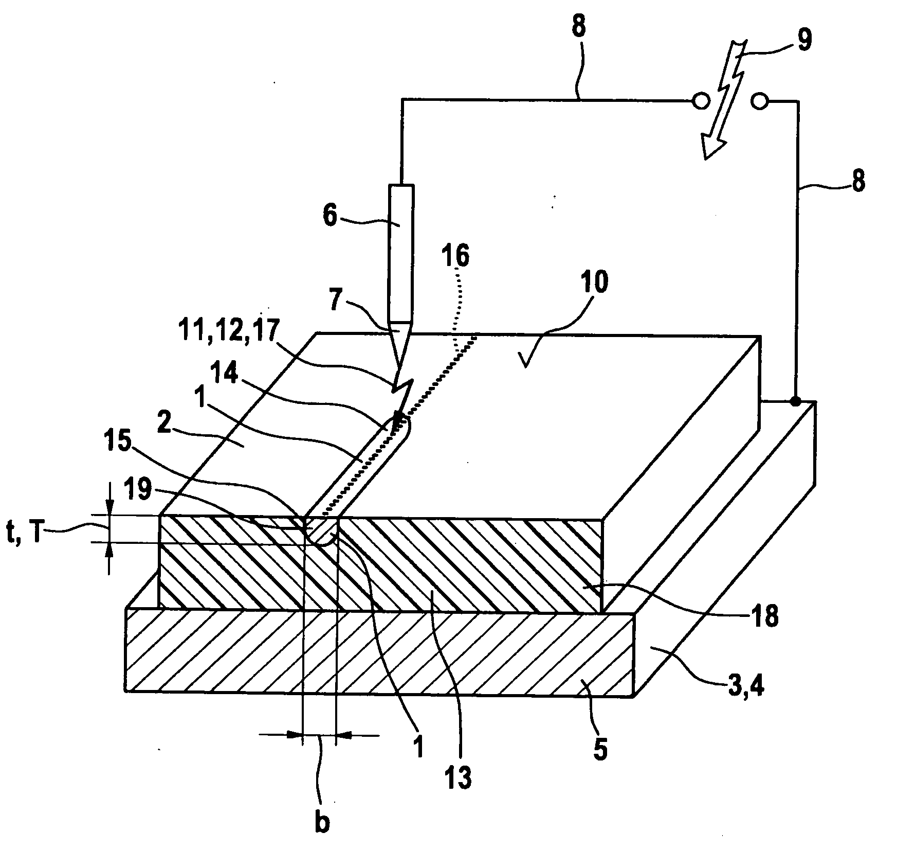
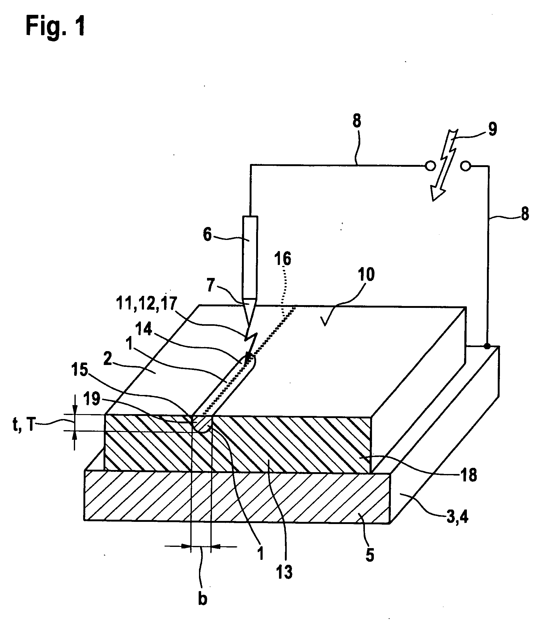
[0016]FIG. 1 shows a schematic representation of the method for producing an electrically conductive path 1 on a plastic component 2. To do this, plastic component 2 is placed on an electrically conductive carrier 3, foe instance, a metal plate 4. In this instance, carrier 3 forms an electrical antipole 5 to an electrical conductor 6, that is situated displaceably above plastic component 2, and that is preferably developed in the form of a spark tip 7 or has a spark tip 7. Between antipole 5 and spark tip 7, an electric field is generated, particularly via a high voltage generator 9 that is connected using electrical connections 8. Since plastic component 2 is conductively lying upon antipole 5, the electric field forms between spark tip 7 and a top side 10 of plastic component 2. If the field strength is sufficiently high, the striking of a spark 11 occurs between spark tip 7 and plastic component 2, in such a way that an electrical spark 12 is applied to top side 10 of plastic com...


PUM

PropertyMeasurementUnit
Electrical conductivityaaaaaaaaaa
Depthaaaaaaaaaa
Energyaaaaaaaaaa

Abstract

In a method for producing an electrically conductive path on a plastic component, the plastic material of the plastic component is converted into a conductive substance using an energy application that is guided along the path.

Description

BACKGROUND OF THE INVENTION[0001]1. Field of the Invention[0002]The present invention relates to a method for producing an electrically conductive path on a plastic component. The present invention also relates to an electric circuit having an electrically conductive path, the electric circuit being situated on a plastic substrate.[0003]2. Description of Related Art[0004]Electronic circuits occur in all fields of modern life. Especially in motor vehicle technology, many sensors and actuators are used in modern vehicles that have to be sealed and encased from their environment, to protect them from the influence of atmospheric conditions. Particularly on their inside, these components require current bars in the widest sense, since on their insides various components have to be connected to one another, and / or a current line is required in general. In the related art, lead wires, printed-circuit traces made of the most different metals, especially copper, wires, etc., of all possible...

Claims


Application Information

Patent Timeline
IPC IPC(8): H05K1/09H05K3/00
CPCH05K1/0284H05K3/105H05K3/301H05K3/325H05K2201/09045H05K2203/1136H05K2201/1059H05K2203/0121H05K2203/105H05K2203/107H05K2201/09118
Inventor HAUTMANN, NIKOLAUS
Owner ROBERT BOSCH GMBH
Why Eureka
Try Eureka