

System appliance and cartridge for personal body care
- Summary
- Abstract
- Description
- Claims
- Application Information
AI Technical Summary
Benefits of technology
Problems solved by technology
Method used
Image

Examples
first embodiment
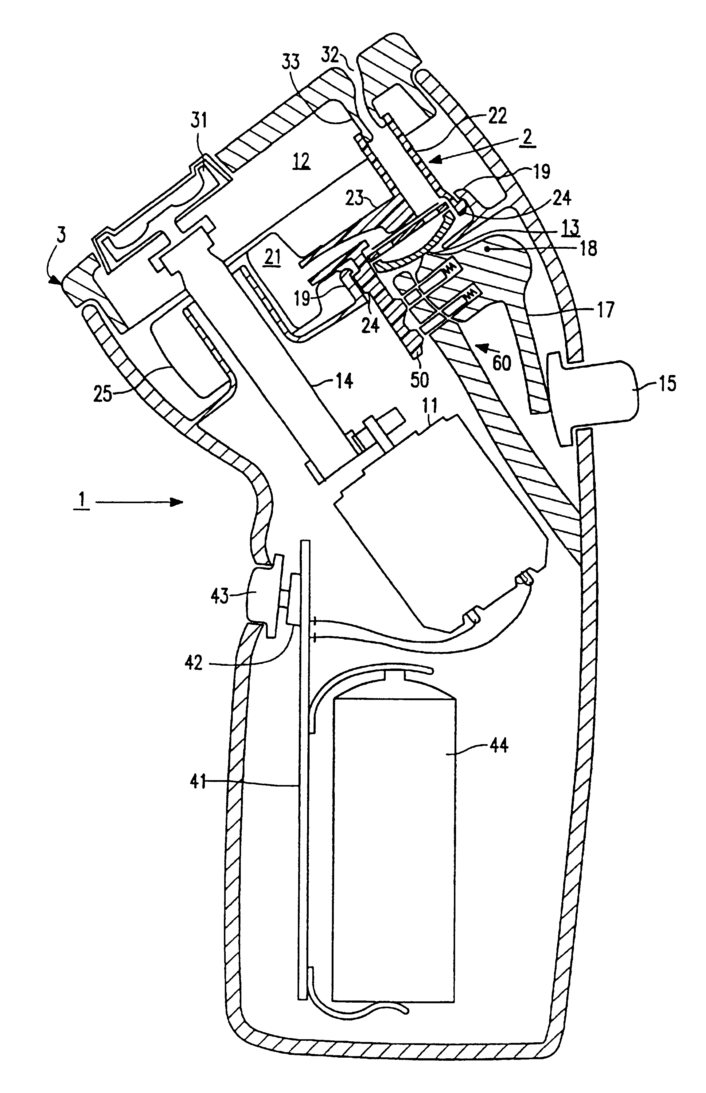
FIG. 1 shows the system in accordance with the invention. The system comprises an electric shaver 1 and a cartridge 2 accommodated in a chamber 12 of the shaver 1. The shaver 1 comprises a treatment device, in the present case a shaving head 3 having drivable cutters 31 and an electric motor 11 for driving the cutters 31 via a coupling pin 14. The cartridge 2 comprises a diaphragm pump 23 and a reservoir 25 having a space 21 for holding an auxiliary fluid. This auxiliary fluid preferably has a lubrication component for reducing the friction between the shaving head 3 and the skin of a user and is preferably a shaving lotion. The cartridge 2 has an outlet channel 22 for applying the auxiliary fluid. The shaver 1 further has an interface for coupling the cartridge 2. The interface of the shaver 1 comprises hooks 19 which engage with hooks 24 of an interface of the cartridge 2. The hooks 19 and 24 have been shaped in such a manner that mounting and removal of the cartridge 2 requires s...
second embodiment
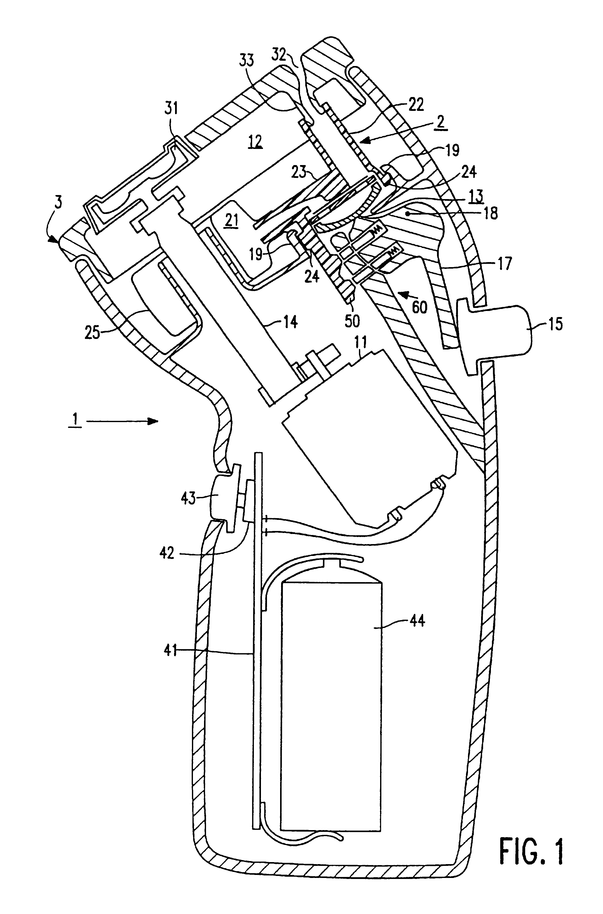
FIG. 2 is a diagrammatic representation of a part of the invention, in which an actuating function is blocked. In this embodiment a slide 117 for the actuation of a pump 123 is blocked by means of a blocking device 160. The blocking device 160 further comprises a blocking element 161, which is held in a blocking position by a resilient element 162. In this blocking position the actuation of the pump is blocked in that the blocking element 161 forms a stop for a projection 118 on the slide 117. The advantage of mechanically blocking the slide 117 is that the user feels that the pump function is blocked. Thus, it is avoided that he draws the conclusion that the cartridge is empty or that clogging has occurred.
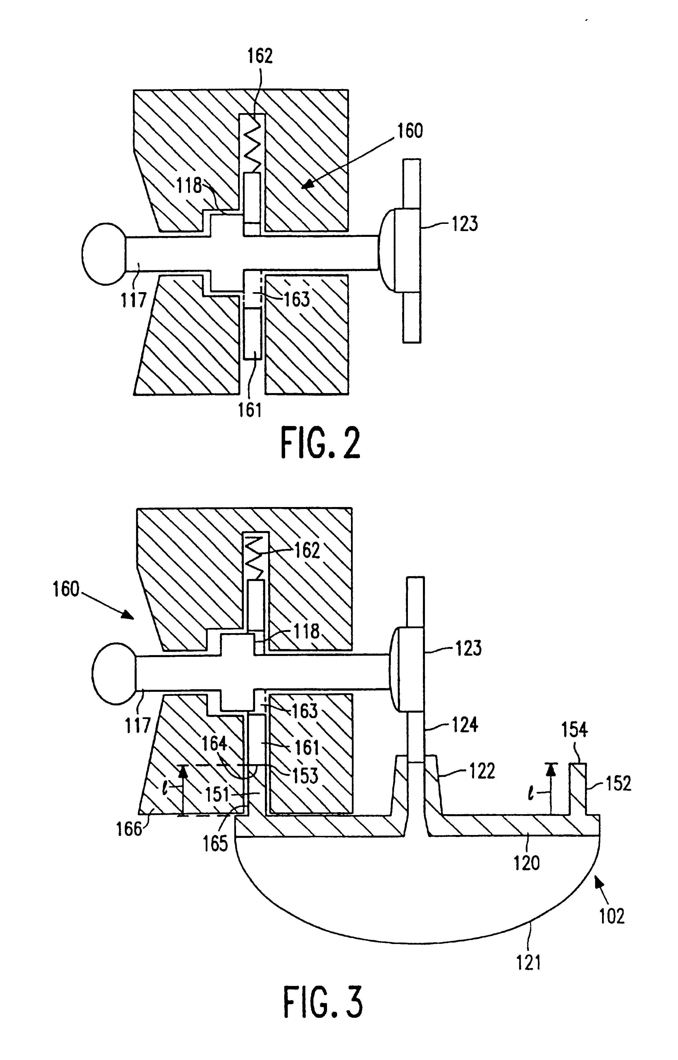
FIG. 3 is a diagrammatic representation of a part of the second embodiment of the invention, in which the actuating function is not blocked. In a non-blocldng position of the blocking element 161 an opening 163 in the blocking element 161 is positioned in such a manner that the p...
third embodiment
FIG. 4 is a diagrammatic representation of a part of the invention. In this embodiment the key comprises two pins 251 and 252 arranged symmetrically with respect to a coupling element 222. The pins 251 and 252 form parts of a flange 220 which is connected to a flexible pouch, not shown. The blocking device 260 comprises two blocking elements 261 and 262 held in a blocking position by two springs 263 and 264. In this blocking position the blocking elements 261 and 262 block two projections 271 and 272 which form parts of actuating slides 273 and 274, so that the functions controlled by the actuating slides 273 and 274 are blocked. The slides 271 and 272 may be coupled in such a manner that both slides should not be blocked to actuate a function. The blocking elements 271 and 272 may be coupled in such a way that the presence of one of the two pins 251 and 252 is adequate to set the blocking elements 271 and 272 to a non-blocking position.
FIG. 5 is a diagrammatic representation of a p...
PUM
 Abstract
Description
Claims
Application Information